Campbell Scientific CR510 Basic Datalogger User Manual
Page 91
SECTION 7. MEASUREMENT PROGRAMMING EXAMPLES
7-13
CR510
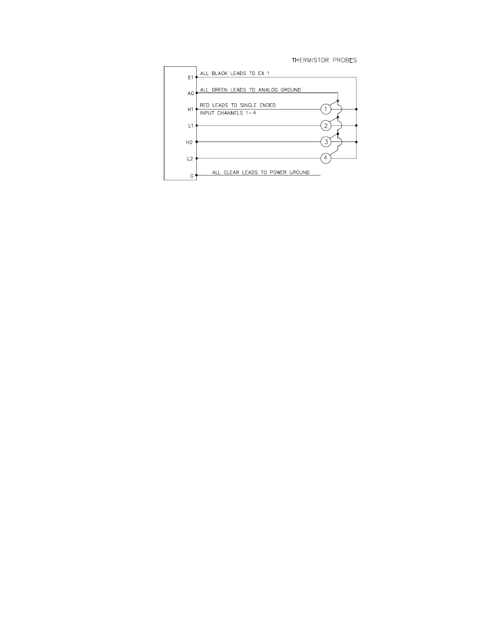
FIGURE 7.12-1. Nonlinear Thermistor Probes Connected to CR510
PROGRAM
01:
Excite-Delay (SE) (P4)
1:
4
Reps
2:
25
±
2500 mV 60 Hz
Rejection Range
3:
1
SE Channel
4:
1
Excite all reps w/Exchan 1
5:
10
Delay (units 0.01 sec)
6: 2000
mV Excitation
7:
1
Loc [ Temp_C_1 ]
8:
.001
Mult
9:
0
Offset
02:
Polynomial (P55)
1:
4
Reps
2:
1
X Loc [ Temp_C_1 ]
3:
1
F(X) Loc [ Temp_C_1 ]
4: -53.784
C0
5: 147.97
C1
6: -218.76
C2
7: 219.05
C3
8: -111.34
C4
9:
23.365
C5
7.13 WATER LEVEL - GEOKON'S
VIBRATING WIRE PRESSURE SENSOR
The vibrating wire sensor utilizes a change in
the frequency of a vibrating wire to sense
pressure. Figure 7.13-1 illustrates how an
increase in pressure on the diaphragm
decreases the tension on the wire attached to
the diaphragm. A decrease in the wire tension
decreases the resonant frequency in the same
way that loosening a guitar string decreases its
frequency.
Vibrating Wire Measurement Instruction 28
excites the "plucking" and "pickup" coils shown
in Figure 7.13-1 with a "swept" frequency. A
"swept" frequency is a group of different
frequencies that are sent one right after another
starting with the lowest frequency and ending
with the highest. The lowest and highest
frequencies are entered by the user in units of
hundreds of Hz. This swept frequency causes
the wire to vibrate at each of the individual
frequencies. Ideally, all of the frequencies
except the one matching the resonant
frequency of the wire will die out in a very short
time. The wire will vibrate with the resonant
frequency for a relatively long period of time,
cutting the lines of flux in the "plucking" and
"pickup" coils and inducing the same frequency
on the lines to the CR510. Instruction 28 then
accurately measures how much time it takes to
receive a user specified number of cycles.
The vibrating wire requires temperature
compensation. A nonlinear thermistor built into
the probe is measured using Instruction 4, a
single-ended half bridge measurement with
excitation, and calculated with Instruction 55, a
fifth order polynomial instruction.
Campbell Scientific's AVW1 Vibrating Wire
Sensor Interface is required between the sensor
to the datalogger. The purpose is twofold:
•
5 or 12 volts can be used as the potential in
the swept frequency excitation, thus
plucking the wire harder than the maximum
2.5 volt switched excitation. The result is a
larger magnitude signal for a longer time.
•
A transformer strips off any DC noise on the
signal, improving the ability to detect cycles.