Ashcroft GC51 - Industrial Rangeable Pressure Transmitter User Manual
Page 24
24
Setting
LCD
Setting
Setting
No.
Item
Display
Description
Range
Default*
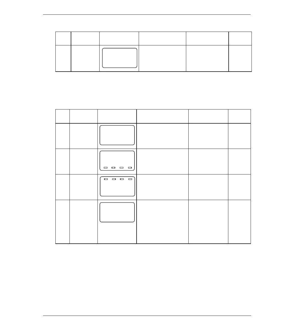
ቢ
Filter
Selection of
1,2,4,8,
moving average
16 times
4
time of pressure
: 8 (times)
Setting
LCD
Setting
Setting
No.
Item
Display
Description
Range
Default*
ባ
Display
Selection of
non:pressure
mode
pressure display
display mode
non
mode : non
Lin: linear
display mode
ቤ
Output
Analog
Pressure
zero point†
output zero point
range:–10
0.0
(4mA) : 10.0 (%F.S.)
to 110%F.S.
ብ
Output
Analog
Pressure
span point†
output span point
range:–10
100.0
(20mA) : 90.0 (%F.S.)
to 110%F.S.
ቦ
Loop
Arbitrary change of
Display: Output
check‡
pressure display and
zero point
0.0
analog output
pressure to
(4mA)
: 10 psi
span point
pressure
Analog output
4 to 20mA
f
8
a
90.0
a
10.0
[010.0
n
non
-
*The default is the factory default.
The following table is the setting. Example 1, Pressure Display Mode,
Section 11-2. This applies when re-scaling in “psi” units.
Note: see page 24 for full menu.
†For setting of zero point and span point in the analog output, input the percent
value over the pressure range.
‡Regardless of applied pressure, the loop check can be activated, refer to
Section 13.4. This example shows the LCD display at the zero point at the start
of loop check start.