Installation drawings – Ashcroft GC51 - Industrial Rangeable Pressure Transmitter User Manual
Page 10
10
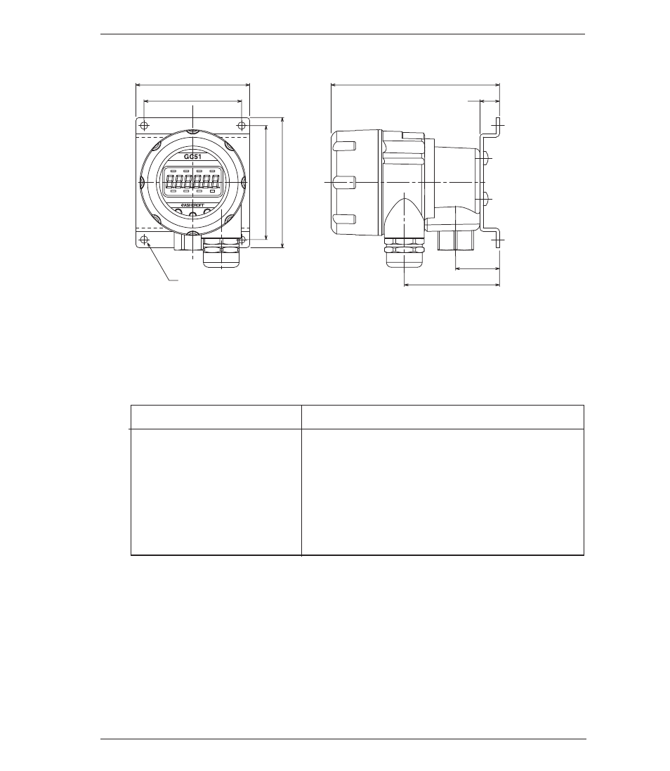
Installation Drawings
Mounting bracket holes
4 - Ø .18
2.76
2.36
2
.7
6
3
.1
5
2.3
1.06
.47
4.1
psi
6.
DIMENSIONS
7.
WIRING
Power supply requirements, 12 -32 Vdc, note installation
recommendations below.
7.1 Cable / Wire Specifications
7.2 Wiring Instructions
• To reduce potential for noise do not run pressure transmitter cable /
wires alongside (same conduit as) high voltage (line power) lines. For
optimum results use dedicated conduit for GC51 cable / wires.
• If using the Cable Gland termination option must use cable within pre-
viously noted diameters to maintain environmental ratings.
Terminal Strip
Cable Requirements
SMKDSP1.5/2-5.08 Phoenix contac
• Two core shielded cable
• Cable outer diameter: 0.35 to 0.47˝
(9-12mm). Required for proper installa-
tion with cable gland option
• Wire Gauge: 14-22 AWG (multi-strand
or solid)
- 2089 Precision Digital Test Gauges (20 pages)
- A4A - Dial Pressure Gauge (2 pages)
- 1082 - Pressure Test Gauge (20 pages)
- 1279 - Receiver Gauges (2 pages)
- 2279 - Duratran® Pressure Transmitter (2 pages)
- 1038A - Duplex Gauge (20 pages)
- 1125 - Differential Pressure Gauge (1 page)
- 1130 - Differential Pressure Gauge (2 pages)
- 1131 - Differential Pressure Gauge (2 pages)
- 1132 - Differential Pressure Gauge (2 pages)
- 1131 - Differential Pressure Gauge (2 pages)
- 1133 - Differential Pressure Gauge (2 pages)
- 1134 - Differential Pressure Gauge (2 pages)
- 2032 - Digital Sanitary Pressure Gauge (32 pages)
- DG25 General Purpose Digital Gauge (16 pages)
- 2074 Digital Industrial Gauge (32 pages)
- 2084 Precision Digital Test Gauge (20 pages)
- A2 - Heavy industrial pressure transmitter (4 pages)
- A2X - Pressure Transmitter (2 pages)
- A4 - Pressure Transmitter (6 pages)
- G2 - High Performance Pressure Transducer (2 pages)
- GC31 - Digital Pressure Sensor (20 pages)
- GC35 - Pressure Sensor (4 pages)
- GC35 - Pressure Sensor (20 pages)
- GC51 - Industrial Rangeable Pressure Transmitter (2 pages)
- GC51 - Industrial Rangeable Pressure Transmitter (4 pages)
- GC55 - Differential Pressure Transducer with Digital Display (24 pages)
- H2 - Precision Pressure Transducer (2 pages)
- K1 - Industrial Pressure Transducer (2 pages)
- KM10 - Compact Pressure Transducer (2 pages)
- KM15 - Compact Pressure Transducer (2 pages)
- KS - Sanitary Pressure Transmitter (2 pages)
- KX - Flush Mount Pressure Transmitter (2 pages)
- DM61 (8 pages)
- DM61 (20 pages)
- CXLdp - Differential Pressure Transmitter (2 pages)
- DXLdp - Differential Pressure Transmitter (2 pages)
- GC30 Ultra-Compact Differential Pressure Sensor (20 pages)
- GC52 - Rangeable wet/wet Differential Pressure Transmitter (2 pages)
- GC52 - Rangeable wet/wet Differential Pressure Transmitter (28 pages)
- GC52 - Rangeable wet/wet Differential Pressure Transmitter (16 pages)
- GC52 - Rangeable wet/wet Differential Pressure Transmitter (40 pages)
- GL42 - Low Differential Indicating Pressure Transmitter (4 pages)
- IXLdp - Low Differential Pressure Transmitter (2 pages)