Appendix f. pin lists – MagTek MICR Plus RS-232 User Manual
Page 65
57
APPENDIX F. PIN LISTS
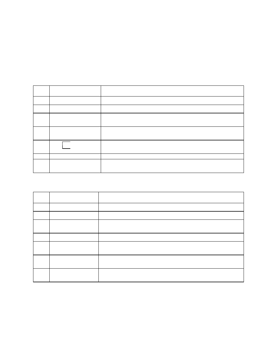
The pin list for the DB25 Interface Cable is shown in Table F-1, and the pin list for the DB9
Interface Cable is shown in Table F-2.
Table F-1. DB25 Interface Cable Pin List
PIN SIGNAL
(Host as Reference)
DESCRIPTION
2
TXD
Transmitted Data. Transmits data from the Host to the MICR Plus.
3
RXD
Received Data. Receives data from the MICR Plus to the Host.
4
RTS
Request to Send. Sends a signal to the MICR Plus to indicate that
the Host is ready to receive data.
5
CTS
Clear to Send. Receives a signal from the MICR Plus to indicate
that the MICR Plus is ready to send data.
6
8
DSR
DCD
Data Set Ready. Receives a signal from the MICR Plus to indicate
that the MICR Plus is active, i.e., power is on.
7 GND
Ground
20
DTR
Data Terminal Ready. Transmits a signal to the MICR Plus to
indicate that the Host is active, i.e., power is on.
Table F-2. DB9 Interface Cable Pin List
PIN
SIGNAL
(Host as Reference)
DESCRIPTION
2
RXD
Received Data. Receives data from the MICR Plus to the Host.
3
TXD
Transmitted Data. Transmits data from the Host to the MICR Plus.
4
DTR
Data Terminal Ready. Transmits a signal to the MICR Plus to
indicate that the Host is active, i.e., power is on.
5 GND
Ground
6
DSR
Data Set Ready. Receives a signal from the Host to indicate that the
MICR Plus is active, i.e., power is on.
7
RTS
Request to Send. Sends a signal to the MICR Plus to indicate that
the Host is ready to receive data.
8
CTS
Clear to Send. Receives a signal from the MICR Plus to indicate that
the MICR Plus is ready to send data.