Low-voltage halogen pendant no. 5508, Assembly instructions for – Holtkoetter 5508 User Manual
Page 2
e-mail: [email protected]
www.holtkoetter.com
ASSEMBLY INSTRUCTIONS FOR
Major lamp parts manufactured in Germany by Holtkötter Leuchten GmbH.
Bulbs manufactured in Germany by Osram GmbH. Final assembly by Holtkötter in South Saint Paul, MN.
Holtkötter
®
and Holtkötter Leuchten
®
are registered trademarks of Holtkötter. All Rights Reserved.
© Holtkötter
Please make sure that the following parts for your low-voltage pendant are
enclosed:
1. Fixture including ceiling canopy, frame and counterweight.
2. Additional backplate and universal crossbar strap
3. Glass shades
4. Bulbs for 5508/8: 8 ea x 20 Watt Halostar by Osram, GY6.35 base.
Order Code: 9250*020-HSTAR
This fixture utilizes an electronic, line-voltage (120 V input) to low-voltage (12 V output)
transformer by LIGHTECH rated at 175 Watts, allowing for a 20 Watt maximum per bulb.
If you are planning to use a dimmer with this fixture, we recommend using a Lutron ELV
(electronic low voltage) style dimmer.
NOTE: The electronic transformer by LIGHTECH is equipped with an automatic reset switch. If
the fixture is not working or has created a short, disconnect the power to the fixture and the
transformer will reset itself.
Be sure to turn off the circuit breaker before installing this fixture.
Dry location only.
THIS PRODUCT MUST BE INSTALLED IN
ACCORDANCE WITH THE APPLICABLE
INSTALLATION CODE BY A PERSON FAMILIAR
WITH CONSTRUCTION AND OPERATION OF
THE PRODUCT AND THE HAZARDS INVOLVED.
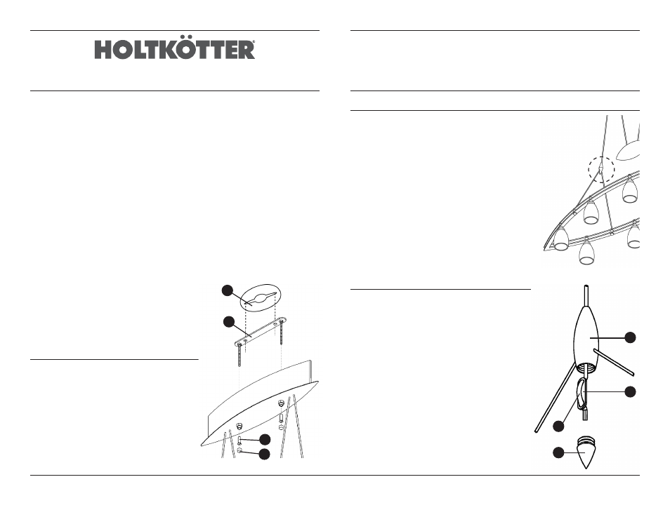
Mounting Instructions (Diagram 1)
Parts used:
A) Round 5” decorative plate with universal crossbar
B) Long metal strap with screws
C) Two brass tubular nuts
D) Two decorative knobs.
Mounting Instructions, continued
1. Disconnect power to the box before installation.
2. Remove decorative knobs (D) and the brass tubular nuts
(C) that are located under the decorative knobs (D).
3. Remove the long metal strap (B) located on the top of
canopy.
4. Mount the round decorative plate (A) to the metal strap
with screws provided on the universal crossbar strap, then
mount the assembled piece to the outlet box.
5. Connect the wires from the fixture with the wires in the
outlet box according to generally accepted electrical
standards. Determine the polarity of the cord by rubbing
it with your thumb. One side will feel smooth (= hot/black)
and the other side will feel rough (= cold/white).
6. Slide the canopy over the metal strap and secure with
brass tubular screws (C).
7. Finally put decorative knobs (D) on the bottom of the
canopy.
Fixture Cable Length Adjustment (Diagram 2)
This low-voltage pendant cannot be lengthened in the field.
Due to the nature of this support system, fixtures requiring
longer support cables will have to be special ordered.
This fixture is supported by two separate cables connected
to the fixture at the finished cable holder (E). The vertical
cable can be shortened.
1. Locate the nut (F) at the bottom of the cable holder.
Take the weight off the fixture and unscrew the nut (F).
2. Pull the vertical cable (G) down to reveal the cable
guide (H). Pull enough cable through the guide to
correct the height. Leaving between 3/4” and 1” of
cable past the cable guide (H), cut the support cable
off.
3. Pull the vertical cable (G) back up into place.
4. Screw the cable holder nut (F) back in place.
Diagram 2
Location
Low-voltage Halogen Pendant
No. 5508
A
B
C
D
Diagram 1
E
G
F
H
Diagram 2