Post calibration actions 6-10, Rf power/alc calibration adjustments – Anritsu 373XXA User Manual
Page 90
quence: H/W CALIBRATIONS, and then SOURCE ALC
CALIBRATION (below).
Step 3.
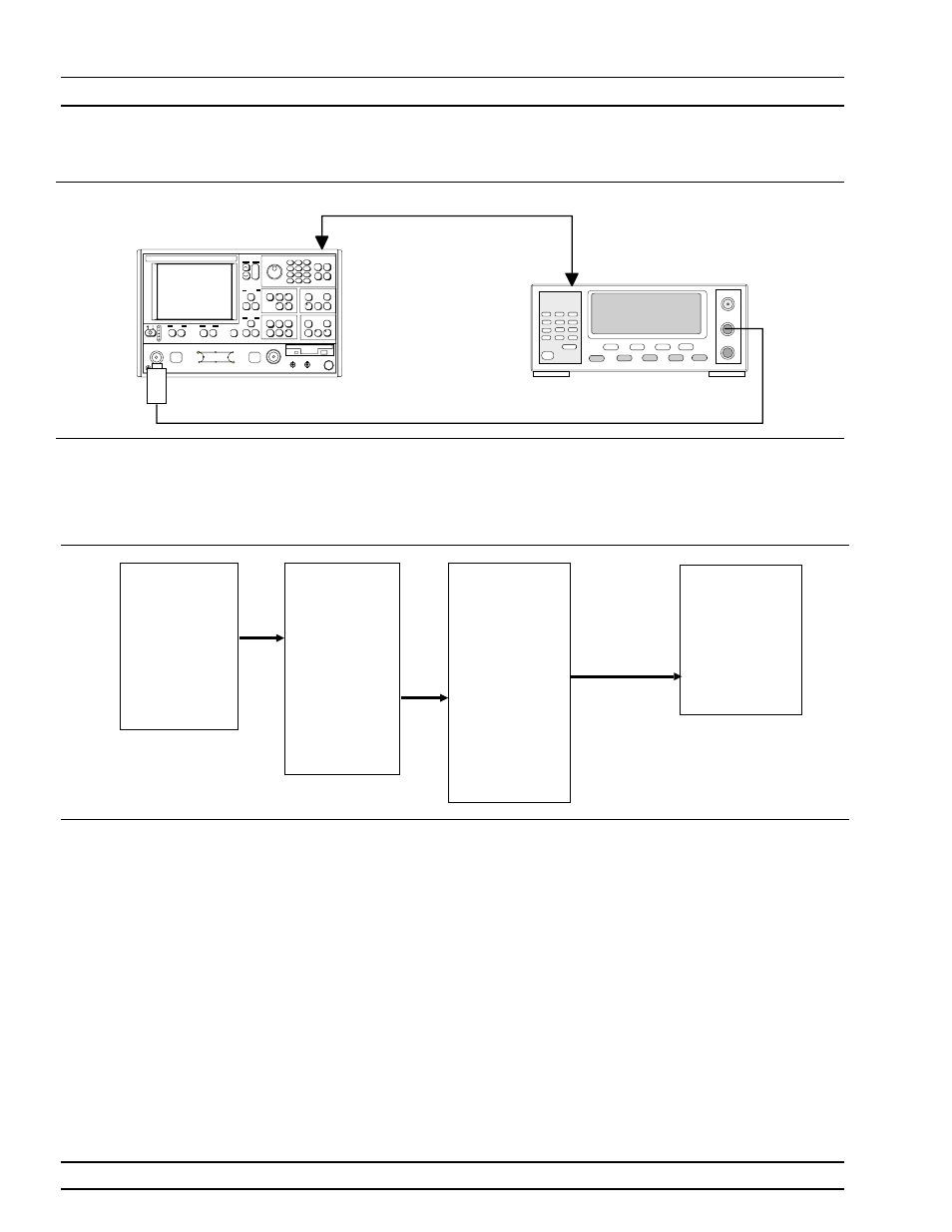
Follow the directions displayed on the screen to set-up and
connect the power meter to the 373XXA. Refer also to Fig-
ure 6-2. Select START ALC CALIBRATION from menu.
Step 4.
Follow the directions displayed on the 373XXA CRT screen,
until calibration is completed.
Step 5.
If the software allows a Port 2 ALC Calibration, perform it
now.
Post Calibration
Actions
After the calibration process is completed, perform the following ac-
tions, as appropriate:
RF POWER/ALC CALIBRATION
ADJUSTMENTS
6-10
373XXA MM
7
8
9
4
5
6
1
2
3
0
.
-
SC6230 Sensor
ANRITSU 373XXA
VNA
Dedicated GPIB
ANRITSU ML24XXA
Power Meter
Figure 6-2.
Equipment Set-Up for RF Power/ALC Calibration
OPTIONS
TRIGGERS
REAR PANEL
OUTPUT
DIAGNOSTICS
MULTIPLE SOURCE
CONTROL
PRESS
SELECT
DIAGNOSTICS
START SELF TEST
READ SERVICE LOG
INSTALLED OPTIONS
PERIPHERAL TESTS
TROUBLESHOOTING
(FOR SERVICE
ONLY)
H/W CALIBRATIONS
(FOR SERVICE
ONLY)
PRESS
SELECT
HARDWARE
CALIBRATIONS
(FOR SERVICE
ONLY)
LO1
CALIBRATION
LO2
CALIBRATION
SOURCE FREQUENCY
CALIBRATION
SOURCE ALC
CALIBRATION
DISK OPERATIONS
PREVIOUS MENU
PRESS
SELECT
HARDWARE
CALIBRATIONS
(FOR SERVICE
ONLY)
START SOURCE
FREQ CALIBRATION
PREVIOUS MENU
PRESS
SELECT
Set-Up