Measurement in question troubleshooting – Anritsu 373XXA User Manual
Page 78
NOTE
The procedures for performing pin depth measurements
for the connectors used on ANRITSU products are con-
tained in Appendix C, Connector Maintenance Check Pro-
cedures.
3.
Check the system performance as follows:
q
Perform the Signal Path Tests that are part of the Operational
Tests. Refer to Chapter 3, Operational Tests.
q
Check Match, Directivity, and Dynamic Range as described in
Chapter 4, Performance Verification.
q
Complete the remaining checks described in Chapter 4 (Per-
formance Verification).
MEASUREMENT IN QUESTION
TROUBLESHOOTING
5-24
373XXA MM
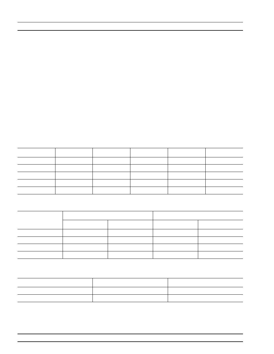
Frequency
SQM In
SDM Out
MUX J4
MUX J1
Buffer Amp In
20 GHz
NA
+18
+6
NA
-
26
37 GHz
NA
+20
+4
NA
-28
40 GHz
+19
NA
NA
+14
-28
50 GHz
+18
NA
NA
+14
-23
65 GHz
+16
NA
NA
+10
-26
Table 5-6. Typical Reference Signal Values in dBm
Wire Color
Below 38 GHz
Above 38 GHz
S21
S12
S21
S12
Brown
+2.0
-
3.3
+2.0
+2.0
Black
-
6.7
+1.6
+1.6
+1.6
White
+1.6
-
6.8
+1.6
+1.6
Grey
-
3.3
+2.0
+2.0
+2.0
Table 5-7. Typical Transfer Switch Voltages (CW, Single Channel Display)
Wire Color
Forward
Reverse
Brown
+1.2
-
3.7
Grey
-
3.7
+1.2
Figure 5-8. Typical SPDT Switch Voltages (CW, Single Channel Display)