12 rear panel assembly 8-19, Remove and replace rear panel assembly, Connector torque wrench – Anritsu 373XXA User Manual
Page 133
To replace the Floppy Disk Drive assembly, perform the steps above in
the reverse order.
8-12
REAR PANEL
ASSEMBLY
This paragraph provides instructions for removing and replacing the
Rear Panel Assembly.
Equipment Required Option 11 only):
q
Connector torque wrench (
5
16
in), ANRITSU Model 01-201, or
equivalent.
Preliminary:
q Switch 373XXA power off. Remove the power cord.
q Remove all covers (paragraph 8-3).
Remove/Replace Procedure:
Step 1.
Place the 373XXA in normal (top-side up) position.
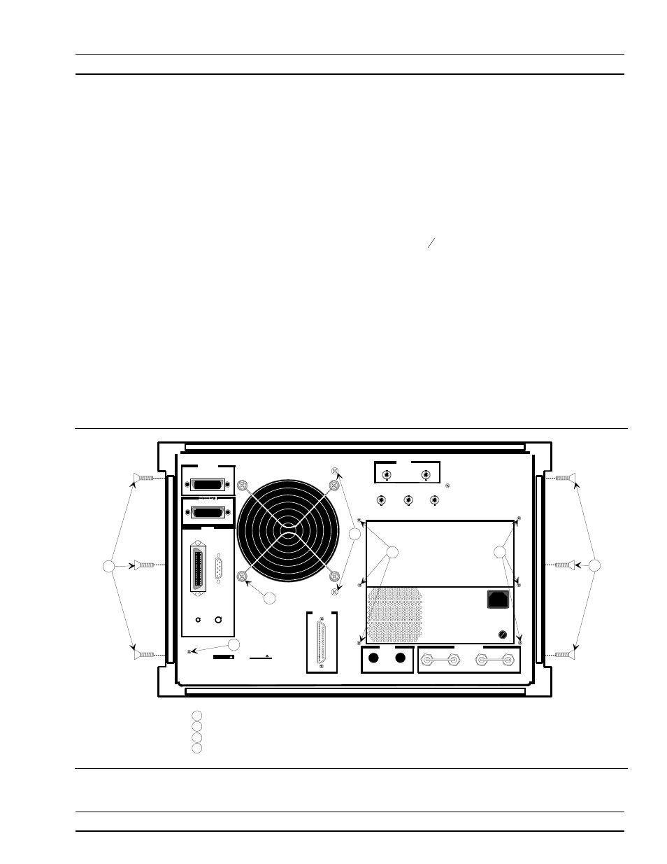
Step 2.
Remove the three screws on each side of the chassis that
fasten to the rear panel assembly. See Figure 8-10.
REMOVE AND REPLACE
REAR PANEL ASSEMBLY
373XXA MM
8-19
External I/O
Reference Extension
RA In
RB In
RB Out
Display
IEEE 488.2 GPIB
10 MHz Ref
Εξτ
Ext
Trigger
Ext
Anlg In
100-120V 5A SB
SAME TYPE AND RATING
85-264VAC 48-63Hz
REPLACE FUSE ONLY WITH
540VA MAX
220-240V 2.5A SB
Bias Fuses
Port 1
Port 2
VGA OUT
Printer Out
CRT Degauss
CRT Brt
WARNING
NO OPERATOR SERVICE-
ABLE PARTS INSIDE
REFER SERVICING TO
QUALIFIED PERSONNEL
CAUTION
FOR CONTINUED FIRE
PROTECTION REPLACE
ONLY WITH SPECIFIED
TYPE AND RATED FUSE
SH1
AH
1
T6
L4
SR1
RL1
PP1
DC
1
DT1
C0
E2
Refer to manual
for GPIB address
RAOut
FU
SE
FU
SE
FU
SE
FU
SE
FU
SE
FU
SE
1n ±5dBm 50
Ω
Out 0dBm 50
Ω
Ext
Anlg Out
1
2
4 PL
1
1
3
3
4
Rear Panel Assembly screws (par 8-11)
Fan Assembly screws (par 8-12)
Power Supply Assembly screws (par 8-13)
A18 Rear Panel PCB screw (par 8-14)
1
2
3
4
Figure 8-10.
Location of Mounting Screws for Rear Panel Assemblies