Typical wiring, Figure 3-2: current sourcing – AMETEK 953 VMAX LDT User Manual
Page 9
9
1080 N. Crooks Road • Clawson, MI 48017 • 800.635.0289 • Phone 248.435.0700 • Fax 248.435.8120 • www.ametekapt.com
AUTOMATION & PROCESS TECHNOLOGIES
®
Typical Wiring
Figure 3-2 shows two common methods for wiring the
953A to a customer supplied interface device, such
as a PLC or panel meter. The two different methods
are commonly referred to as Single Ended Input or
Differential Input. Differential Input is the preferred
wiring method.
With the Differential Input, the Analog Common wire is
connected to the customer supplied input device and
the Power Supply Common is wired separately to the
customers supplied power source. When wired using
the Differential method, the electrical noise and
voltage offset errors produced by the currents running
through the Power Supply Common are eliminated.
The Power Supply Common and Analog Common are
internally connected inside of the 953A VMAX LDT.
The 953A-C is current sourcing which allows
the current to flow from the LDT into the users
equipment.
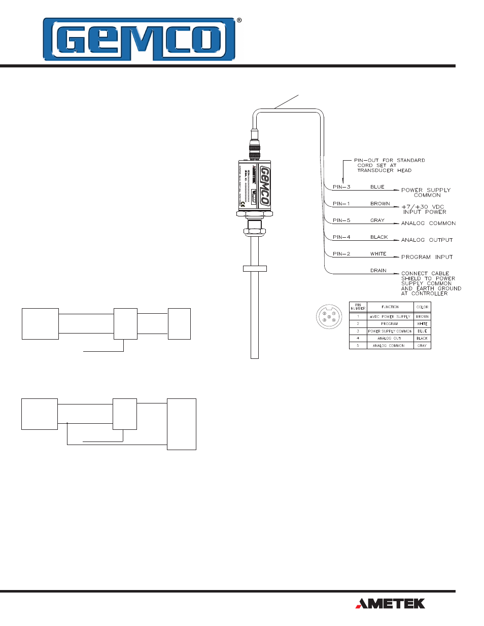
Figure 3-3: Wiring for Connector
Option "S", 5 Pin Micro
Figure 3-2: Current Sourcing
Power
Supply
7-30 VDC
953A
LDT
+ Input
- Input
Customer
Supplied Power
Power
Supply Common
Position
Output
Position
Common
Program Input
+
_
Power
Supply
7-30 VDC
953A
LDT
+ Input
Common
Customer
Supplied Power
Power
Supply Common
Position
Output
Program Input
+
_
Differential Input
Single Ended Input
3
2
4
1
5
LDT
Connector
View
A
U
T
O
M
A
T
IO
N
&
P
R
O
C
E
S
S
T
E
C
H
N
O
L
O
G
IE
S
Cable # 949011LXX
NOTE: XX= Length in feet
TM