AMETEK 953 VMAX LDT User Manual
Page 6
6
1080 N. Crooks Road • Clawson, MI 48017 • 800.635.0289 • Phone 248.435.0700 • Fax 248.435.8120 • www.ametekapt.com
AUTOMATION & PROCESS TECHNOLOGIES
®
• An O-ring is provided at the base of the LDT’s
mounting hex for pressure sealing. The O-ring seal
was designed to meet Mil-Std-MS33656. Refer to
SAE J514 or SAE J1926/1 for machining of mating
surfaces.
• A chamfered rod bushing in front of the magnet
may be required. It is recommended that a
chamfered rod bushing be used with LDTs having
a rod 60.0” or longer. This bushing will prevent
wear on the magnet assembly (wear occurs as the
piston retracts from extended lengths). This rod
bushing should be manufactured from a high wear
polymer, such as Teflon®.
• It is recommended the bore for the cylinder
piston rod have an inside diameter of at least
0.50”. The LDT rod has an outside diameter of
0.405”. Use standard practices for machining and
mounting these components. Consult the cylinder
manufacturer for details on applicable SAE or
military specifications.
It may be necessary to perform machining and
mounting operations on the hydraulic cylinder before
installing the LDT. Consult the information and
specifications provided by the cylinder manufacturer
before beginning the following steps:
1. Unscrew the LDT’s jam nut from the threads
protruding from the hex mounting base.
2. Position the non-ferrous spacer against the
piston face, followed by the magnet, and then the
chamfered rod bushing if the LDT’s rod is 60.0” or
longer in length.
3. Insert non-ferrous screws through the chamfered
rod bushing (if used), magnet, and non-ferrous
spacer. Secure items by tightening screws.
If the leading edge of the magnet will come closer
than 2.0” from the base of the LDT’s hex head
when the piston rod is fully retracted, it will be
necessary to counterbore the magnet assembly
into the piston rod. Both the standard 1.29” four-
hole magnet assembly (P/N SD0400800) and
the 1.0” magnet assembly (P/N SD0410300) are
designed for counterbored mounting applications.
If it has a 1.0” magnet assembly, a snap ring will
be needed to hold it in place.
4. Insert the LDT’s rod into the hole of the hydraulic
cylinder’s mounting bracket.
The protective Plug may need to be removed from
the hydraulic cylinder before inserting the LDT. The
end cap should contain a 3/4-16 UNF-2B threaded
hole. Screw the LDT into this hole using the
threads protruding from the LDT’s hex mounting
base.
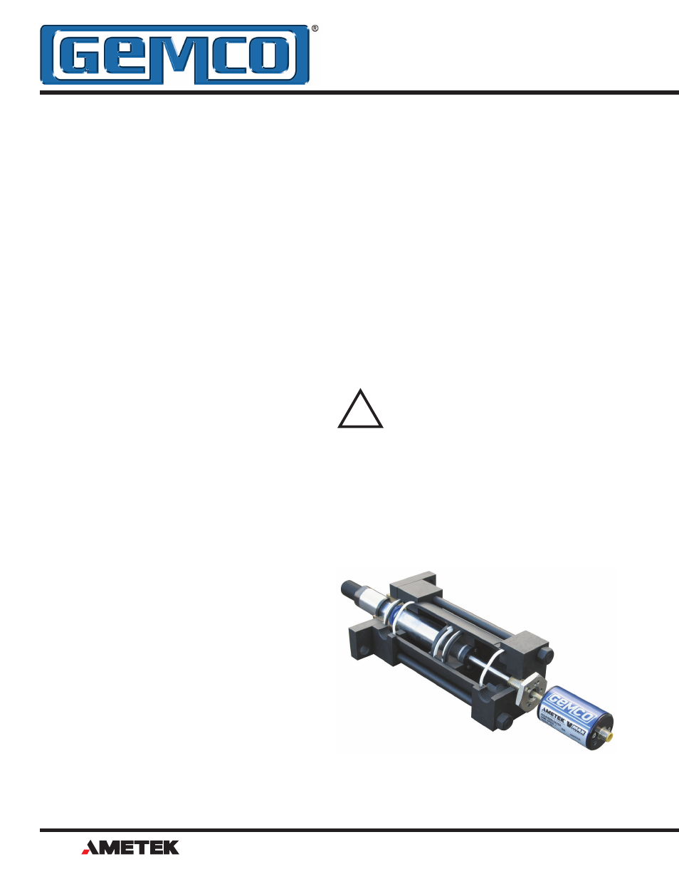
WARNING: Do not use the blue
aluminum cover of the head assembly
to tighten the LDT within the bracket
(see Figure 2-1). This may damage
the LDT and will void your warranty. To tighten
the LDT within the bracket, use the 1.75" hex
mounting base on the head assembly.
With the LDT properly installed inside the hydraulic
cylinder, it may be necessary to assemble parts of the
hydraulic cylinder. For assistance in this task, refer to
the information provided by the cylinder manufacturer.
!