Appendix b: part numbering – AMETEK 953 VMAX LDT User Manual
Page 15
15
1080 N. Crooks Road • Clawson, MI 48017 • 800.635.0289 • Phone 248.435.0700 • Fax 248.435.8120 • www.ametekapt.com
AUTOMATION & PROCESS TECHNOLOGIES
®
Appendix B: Part Numbering
to power the LDT. When powering more than one
VMAX on a single power supply, remember that each
unit requires approximately one watt of
power. The amount of current draw will vary based on
the input voltage used. To calculate the current draw
for a particular LDT, divide the LDT wattage by the
input voltage. For example, 1 watt divided by 24 VDC
equals 41.6mA.
If the LDT is not operating properly, the LDT’s cable
may have an open or short, or the power supply is not
supplying sufficient power. To verify this:
1. Turn the power supply off.
2. Remove the mating connector from the LDT.
3. Turn the power supply on.
4. Using a digital voltmeter, check across Power Supply
Common and customer supplied power (+VDC) on
the mating end of the cable for a level between 7 and
30 VDC.
Appendix B: Part Numbering
NOTE: LDT’s with integral cable assemblies
should be checked for proper voltage at the power
supply terminals. This cable assembly cannot be
removed from the LDTIf the reading is between 7
and 30 VDC, turn power supply off and go to step
7. If the reading is below 7 VDC, either the power
supply is not providing enough power or the LDT’s
cable possibly has a short or open. A reading of
no voltage or minimal voltage (less than 5 volts)
may be due to a short or open in the cable. If the
reading is not between 7 and 30 VDC, go to step
5. If the reading is above 30 VDC, adjust power
supply or replace.
5. Turn the power supply off.
6. Check the continuity of the individual wires of
the cable between the power supply and the
LDT. Check for continuity from one end of the
cable to the other. Also, verify that no shorts
exist between pins.
7. Reconnect the mating connector to the LDT.
953A
0120
V0
X
Stroke Length
Insert stroke length to 0.1 inch. Enter as a four-
place number. Example: A 12.0” stroke enters as
0120.
OR
Insert stroke in millimeters to 1mm. Enter as a
four-place number. Example: 305mm stroke entered
as 0305M. Metric length includes metric mounting,
M18x1.5. Unless specified otherwise.
S
X
X
Null Zone
X
Standard 2 inches.
N_ Insert non-standard Null
Zone (1.5" Minimum).
Options
X
None
S
Stainless Steel cover and
connector. Only available
with connector options S,
C and H.
Dead Band
X
Standard 2.5 inches.
D_
Insert non-standard Dead
Band (2.25" Minimum).
Output
V0
0 to 10 VDC
V1
10 to 0 VDC
V2
-10 to 10 VDC
V3
10 to -10 VDC
V4
0 to 5 VDC
V5
5 to 0 VDC
V6
-5 to 5 VDC
V7
5 to -5 VDC
C4
4 to 20mA
C2
20 to 4mA
Connector Option
S
Standard 5 Pin, 12mm Euro
C_
Integral Cable Assembly.
Insert length in feet. Example:
C6 = 6 foot cable.
M
6 Pin DIN, MTS Style D60
B
8 Pin DIN, Balluff S32
E
Environmental 10 Pin MS
Connector compatible w/951 &
952 LDTs
w/connector option “E”.
H_
High Temp., Integral cable
assembly 200 C Teflon Cable.
Insert length in feet. Example: H6=
6 foot High Temp Teflon Cable.
o
Optional Housing Style
Mounting Threads
Blank
Raised face hex base
(Standard) - Threads will
be the same as "Units
of Measure" unless
specified otherwise.
R
US Threads with raised
face hex base
F
US Threads with flat
face hex base
M
Metric Threads with
raised face hex base
N
Metric Threads with flat
face hex base
C
Sensor cartridge only
No hex base
NOTE 1: On unsupported stroke
lengths greater
than 4 feet, rod support bracket(s)
and a special magnet
should be used.
NOTE 2: Specify magnet as sepa-
rate line item.
Standard magnet is SD0400800.
VP
Units
Blank Inches
M
Metric Base
and Threads
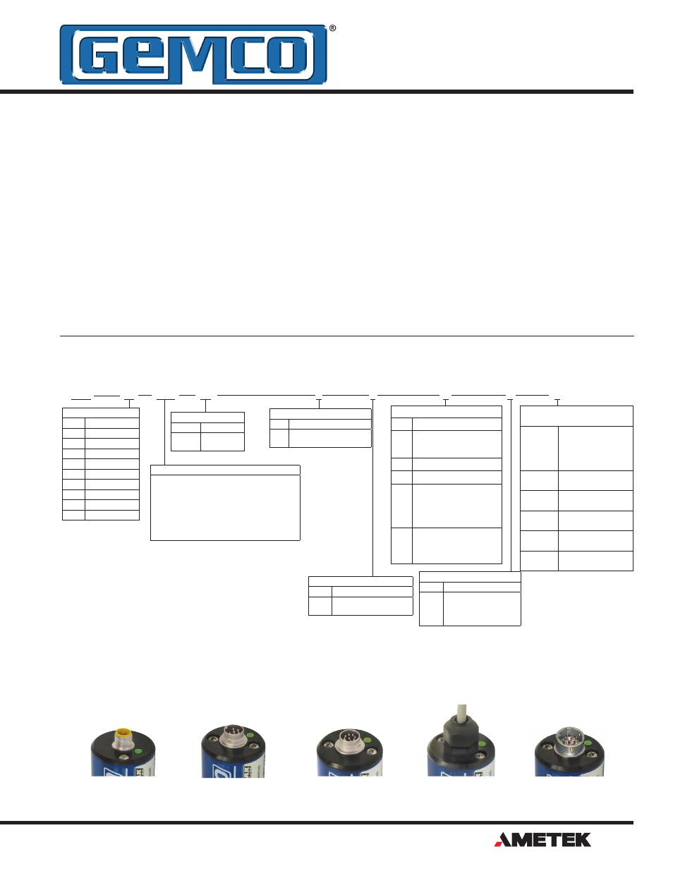
S Connector Style
5 Pin Micro, 12mm Euro
M Connector Style
6 Pin DIN, Fits MTS D60
B Connector Style
8 Pin DIN, Fits Balluff S32
C Connector Style
Integral Cable Assembly
E Connector Style
10 Pin MS Connector,
Fits Gemco 951 & 952 Wiring