Installing the ldt in a hydraulic cylinder, Figure 2-1: mounting the ldt – AMETEK 953 VMAX LDT User Manual
Page 5
5
1080 N. Crooks Road • Clawson, MI 48017 • 800.635.0289 • Phone 248.435.0700 • Fax 248.435.8120 • www.ametekapt.com
AUTOMATION & PROCESS TECHNOLOGIES
®
required. Stress between the magnet and the rod
can cause flexing of the mounting brackets. This
may result in non-linearity.
• LDTs using a split magnet assembly must keep
the diameter of the magnet assembly around the
rod throughout the complete stroke. The diameter
of this magnet assembly should not be more than
0.2” away from the rod. Split magnet assemblies
outside of this range will cause signal loss.
To install the magnet assembly, perform the following
steps:
1. Slide the magnet assembly over the LDT rod.
2. Mount the magnet to the non-ferrous, movable
portion of the device being controlled using non-
ferrous screws.
2.2: Installing the LDT in a
Hydraulic Cylinder
Before installing an LDT in a hydraulic cylinder, note
the following considerations. Items discussed in this
section are found in Figures 1-1 and 2-1.
• A non-ferrous spacer must be used to separate the
magnet assembly from the head of the piston rod.
See Figure 2-2.
• The magnet should not be closer than 2.0” from the
base of the LDT’s hex head when the piston rod is
fully retracted. In instances where space restraints
exist, it may be required to countersink the magnet
into the piston rod. Two magnets are available
for mounting to the piston: the standard 1.29"
in diameter (P/N SD0400800) four-hole magnet
and the 1.0" magnet (P/N SD0410300) designed
exclusively for countersunk mounting applications.
The 1.0" magnet must be secured with a snap ring.
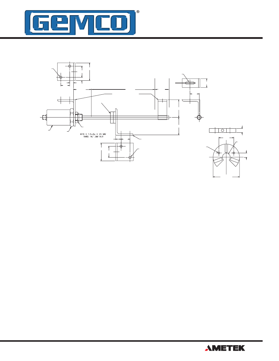
Figure 2-1: Mounting the LDT
BAN D
OPTIONA
OR
L
OPTIONAL
MAGNE T
NUL L
STROK E
DEAD
1.75 HE X
MAGNET MOUNTIN G
KIT (P/N 949005)
PROBE MOUNTING KI T
(P/N 949003)
2.00
2.00
3/4-16 JAM NUT
SUPPLIED W/PROB E
1.00
1.03
.28 X 1.03 SLOT
1.00
.4 4
1.25
2.00
.2 8
2 PLACES
2.00
1.25
1.00
2 PLACES
.2 8
.6 2
PROB E
3/16" X 2" X3" STAINLESS STEEL .
2. MOUNTING BRACKETS ARE MADE FROM
MOUNTING BOLTS.
1. MOUNTING KITS FURNISHED WITH
NOTES: UNLESS OTHERWISE SPECIFIE D
C
L
.3 7
2.50 REF .
.406
1.407
.75 THRU
.38
.187 THRU
(2 PLACES)
S
N
N
N
S
S
S
NOTE: USE THIS MAGNET WITH ROD
SUPPORT BRACKET SD0411100