Chapter 3: wiring, V0/v1 (voltage), C4/c2 (current) – AMETEK 953 VMAX LDT User Manual
Page 8
8
1080 N. Crooks Road • Clawson, MI 48017 • 800.635.0289 • Phone 248.435.0700 • Fax 248.435.8120 • www.ametekapt.com
AUTOMATION & PROCESS TECHNOLOGIES
®
Once the LDT has been installed, wiring connections
can be made. The VMAX has four different connector
options. Please refer to the part number label to help
identify which wiring diagram is correct. There are two
groups of connections that will need to be made. They
are as follows:
• Power Supply Connections
(including grounding and shielding)
• LDT Input/Output Connections
Power Supply/Ground Connections
The 953A VMAX is available with many different con-
nector/wiring options. Refer to part numbering on unit
in question for proper wiring. See Appendex B for part
numbering grid and fiqures 3.3 - 3.9 for wiring details.
Connector option S is an industry standard 5 pin
12mm Euro style cordset with a shield. Option B is an
8 pin DIN with a shield, and option M is a 6 pin DIN
with a shield. To reduce electrical noise, the shield
must be properly used. Connect the cable’s shield to
the controller system GND. The cable shield is NOT
connected at the transducer rod. Always observe
proper grounding techniques such as single point
grounding and isolating high voltage (i.e. 120/240
VAC) from low voltage (7-30 VDC cables).
WARNING: Do not use molded cordsets
with LEDs!
It is preferable that the cable between the LDT and
the interface device be one continuous run. If you are
using a junction box, it is highly recommended that the
splice junction box be free of AC and/or DC transient-
producing lines. The shield should be carried through
the splice and terminated at the interface device end.
NOTE: When grounding the LDT, a single earth
ground should be connected to the Power Supply
Common (circuit ground). The LDT Power Supply
Common should be connected to the Power Supply
Common (-) terminal. The LDT power supply (+VDC)
should be connected to the power supply positive
Chapter 3: Wiring
terminal (+). The LDT cable shield should be tied to
earth ground at the power supply. The LDT analog
common should not be connected to earth ground and
should be used for connection to interface devices
only. For assistance, refer to your LDT’s wiring drawing
in this chapter.
In order for the VMAX to operate properly, the external
power supply must provide a voltage between 7-30
VDC. The power supply must be rated at one watt
minimum. The power supply should provide less than
1% ripple with 10% regulation.
The power supply should be dedicated to the
VMAX to prevent noise and external loads from
affecting it. When powering up more than one
VMAX on a single power supply, each unit will draw
approximately one watt.
3.1: V0/V1 (Voltage)
The LDT generates a voltage output based on position.
The 953 VMAX offers 16 Bits of resolution, and is
fully programmable over the entire active stroke
length. Keep in mind that there is a 2” Null Zone at the
connector end of the LDT and a 2.5” Dead Band at the
other end of the LDT that the magnet must stay out
of at all times. The units come fully programmed from
the factory and do not require re-programming unless
desired.
The analog output is referenced to the analog common
terminal and should not be referenced to any of the
other common terminals. For wiring, see Figure 3-2.
For programming Zero and Span, See Section 3.3.
3.2: C4/C2 (Current)
The LDT generates a current output based on position.
The 953 VMAX offers 16 Bits of resolution, and is fully
programmable over the entire active stroke length of
the LDT. Keep in mind that there is a 2” Null Zone at
the connector end of the LDT and a 2.5” Dead Band at
the other end of the LDT that the magnet must stay out
of at all times. The units come fully programmed from
the factory and do not require re-programming unless
desired.
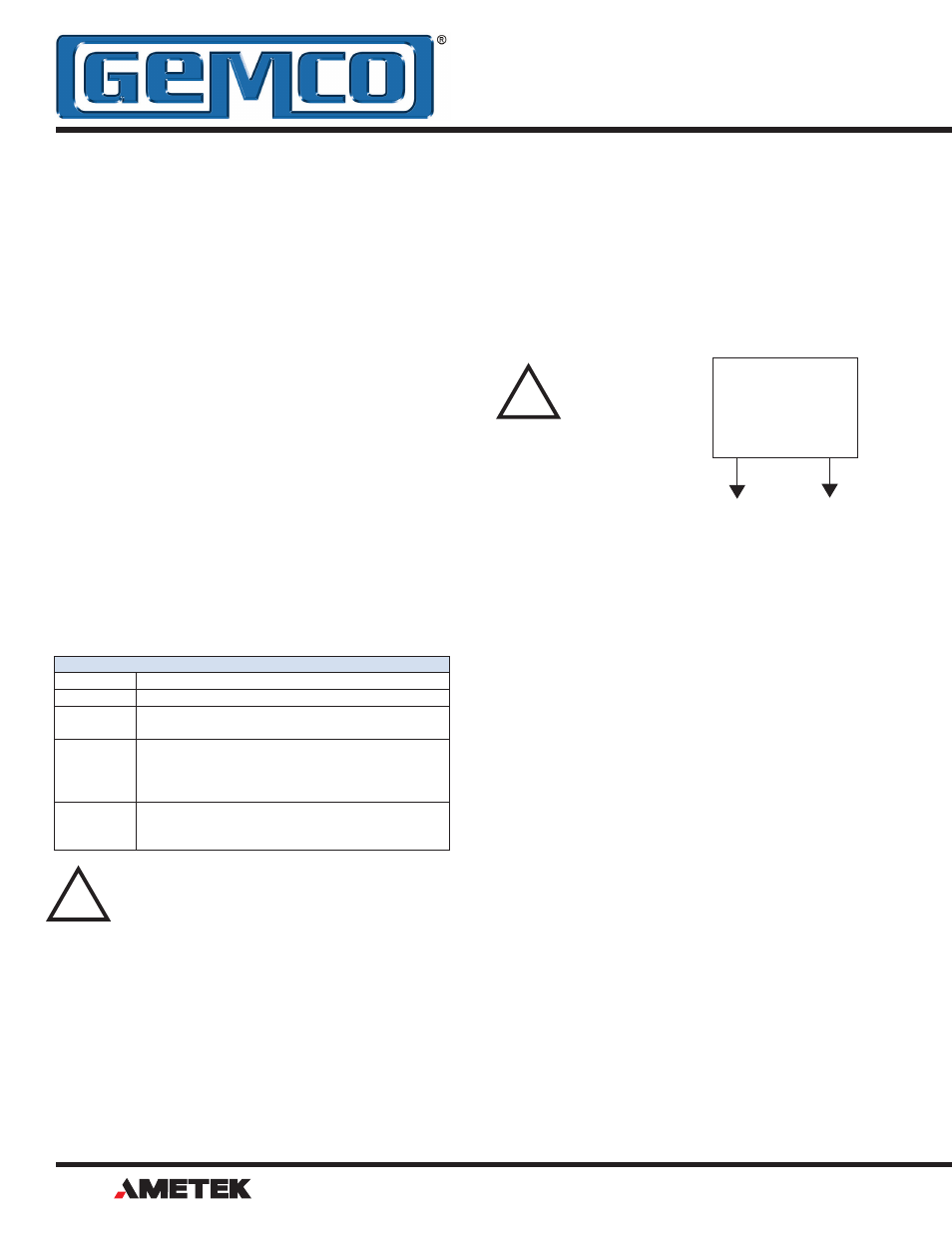
Figure 3-1: Power Supply Wiring
Pin 1 (brown)
Pin 3 (blue)
Single ended
power supply
7-30 VDC
+ COM
WARNING: Do not
route the VMAX
cable near high
voltage sources.
!
!
Diagnostic LED
LED Color Description
None
No power to LDT
Green
Magnet signal detected and within programmed
range.
Yellow
Magnet signal detected, but magnet is outside of
programmed range.
NOTE: Magnet can be programmed in this range
if desired.
Red
No magnet signal detected. Make sure magnet
is on the rod and within the active area. Move
magnet back into the range and cycle power.