Wiring gmw95, Connecting several transmitters on same rs485 line, Connecting several transmitters on same – Vaisala GMW90 User Manual
Page 31: Rs-485 line, Figure 18, Figure 19, Several transmitters on same rs-485 line, Figure 18 wiring gmw95
Chapter 3 ________________________________________________________________ Installation
VAISALA ________________________________________________________________________ 29
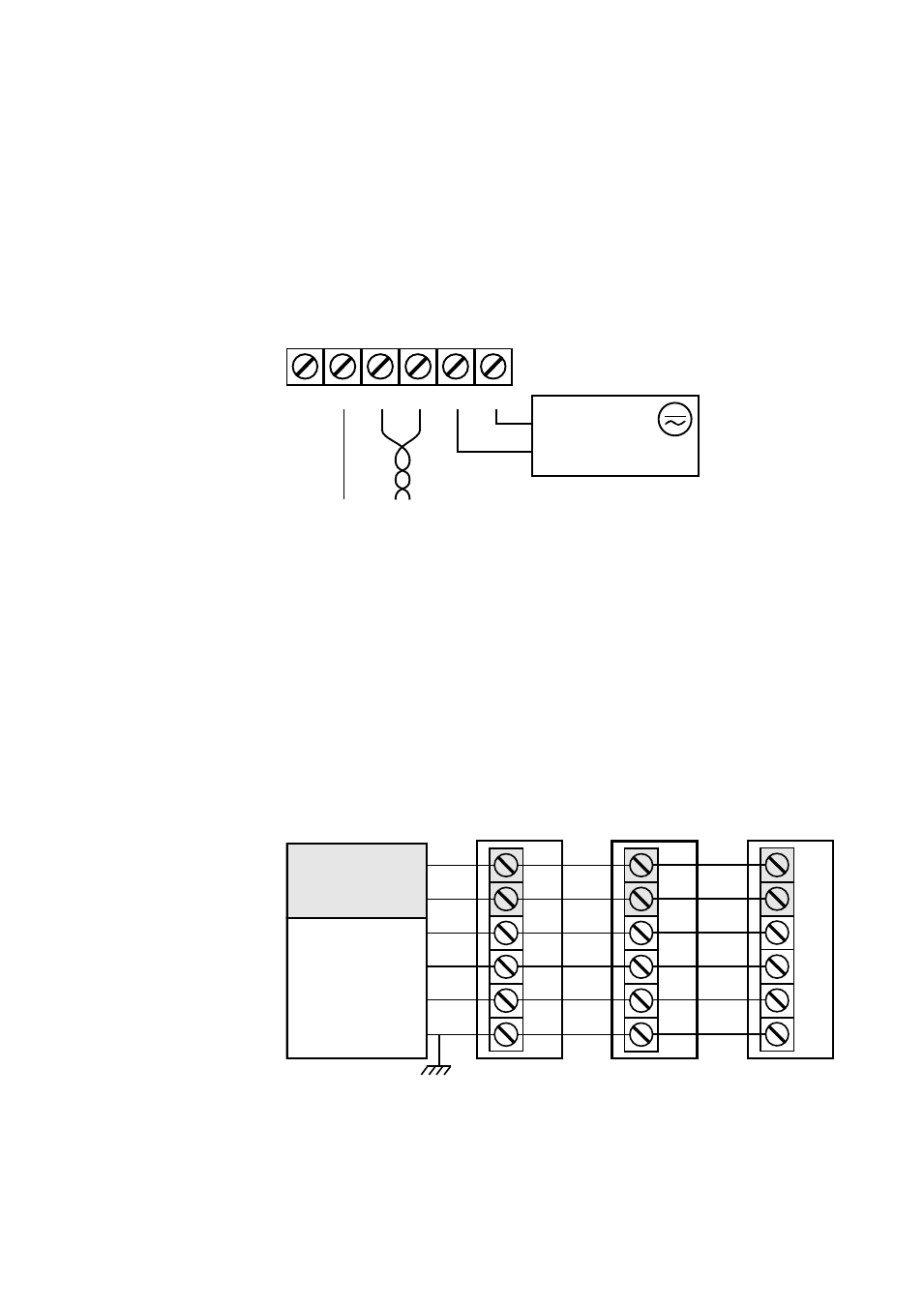
Wiring GMW95
The RS-485 line of the transmitter is isolated from the power supply. A
separate ground reference terminal (GND) is provided for the RS-485
connection.
If you are using a shielded cable, you can use the Shld terminal to hold
the exposed part of the shield. Note that the Shld terminal is floating
(not electrically connected).
1209-014
Figure 18
Wiring GMW95
Connecting Several Transmitters on Same RS-485
Line
Set the RS-485 termination jumper to “ON” on the transmitter that is at
the end of the line. This terminates the line with a 120 Ω resistor. For
location of the jumper, see Figure 4 on page 17.
Connect the cable shield to ground on the building controller side.
1209-015
Figure 19
Several Transmitters on Same RS-485 Line
D-
-Vs
D+
+Vs
+
-
Power supply
18 ... 35 VDC
or 24 VAC ±20%
RS-485
Shld GND
Transmitter
D-
-Vs
D+
+Vs
Shld
GND
Building controller
Transmitter
Transmitter
Power
supply
D-
D+
+Vs
-Vs
GND
SHIELD
RS-485:
BACnet or
MODBUS
master
Connect shield on controller side
Set RS-485
termination jumper
D-
-Vs
D+
+Vs
Shld
GND
D-
-Vs
D+
+Vs
Shld
GND