Installing the mounting base, Wiring, Figure 10 – Vaisala GMW90 User Manual
Page 27
Chapter 3 ________________________________________________________________ Installation
VAISALA ________________________________________________________________________ 25
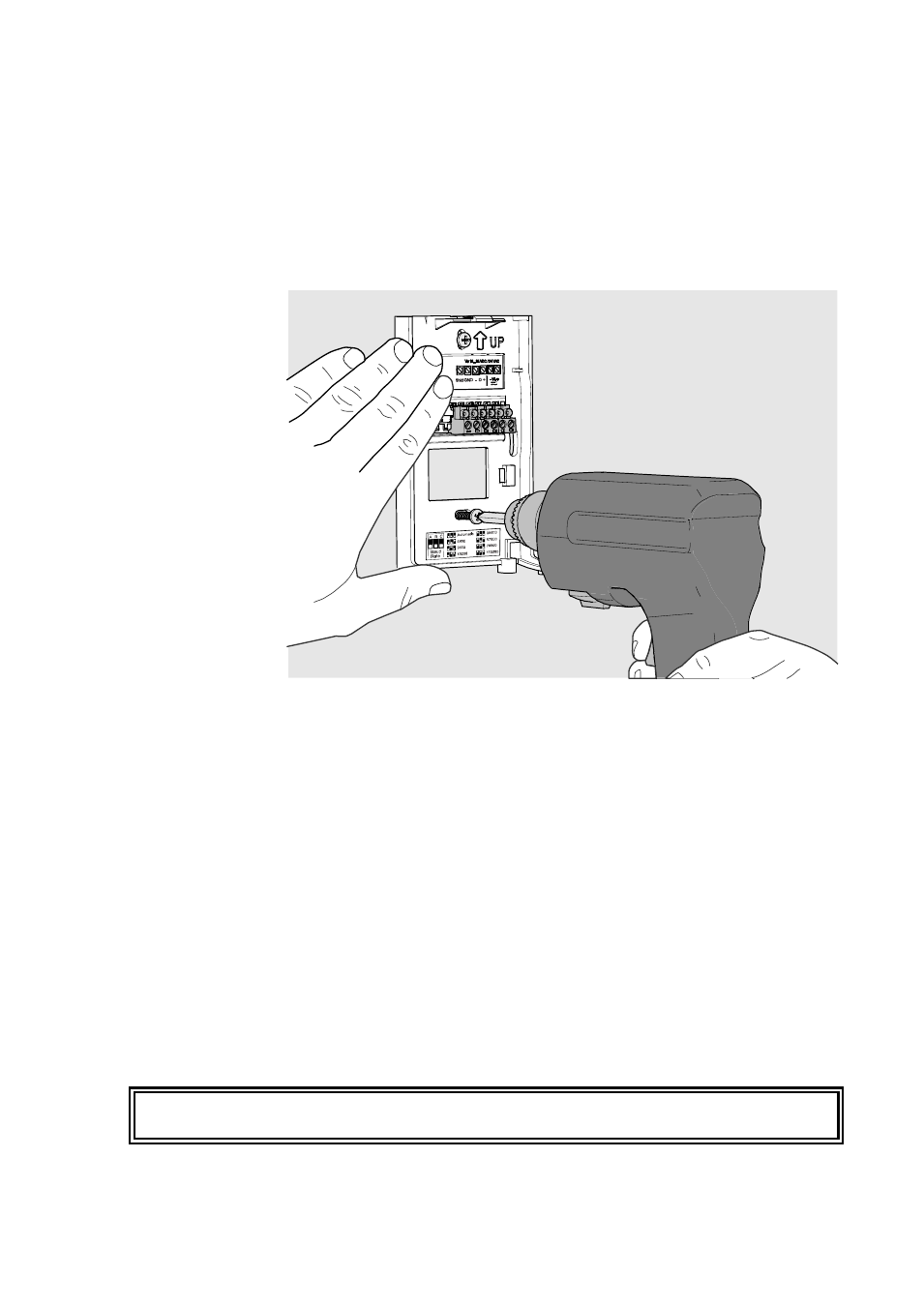
Installing the Mounting Base
Use the mounting holes to attach the mounting base securely. Use at least
two screws (not included). The arrow on the mounting base must point
straight up after installation. Proper orientation is important: air must
flow through the vents on the bottom and top.
1310-043
Figure 10
Installing the Mounting Base
Wiring
Connect the wiring to the screw terminals on the mounting base. The
supply voltage and terminal assignments are model-specific. Max wire
size 2 mm
2
(AWG14).
You can bring the cable to the housing from above or from
behind (recommended). If you are wiring a GMW90 series transmitter
from above, note that the GM10 module takes up significant space inside
the transmitter. To make sure there is enough space to close the
transmitter, use a < Ø 5 mm cable, and route it from the left side of the
mounting base. See Figure 12 on page 26.
After completing the wiring, connect the transmitter body over the
mounting base. Note that mounting bases are model-specific.
WARNING
Connect only de-energized wires.