State CSB 120 54 IFE User Manual
Page 25
25
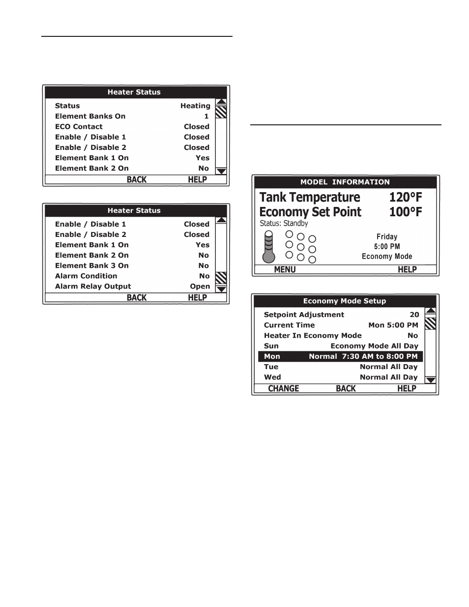
hEAtEr stAtus MEnu
This menu displays non adjustable operational information. This
menu contains more information that can be displayed on one screen
of the LCD display. Use the Up & Down Buttons to navigate to the
bottom of this menu.
top of Menu
Bottom of Menu
status
Displays the current Operating State of the control system. IE:
Heating, Standby, Fault see Table 8.
Element Banks on
Displays the current number of heating element Banks the control
system has energized. Each Bank of elements contains 3 heating
elements.
ECo Contact
Displays the current state of the ECO high temperature limit
switch contacts. The ECO switch is located inside the immersion
Temperature Probe (two red wires).
Enable / disable 1 & 2
Displays the current state, open or closed, of the two Enable/Disable
circuits (J7 socket on the CCB - see wiring diagrams) provided
for external supervisory controls such as building EMS (Energy
Management System). Both of these Enable/Disable circuits must be
closed to “enable” heating operation. If either Enable/Disable circuit is
open for any reason heating operation will be “disabled.” There is a plug
with two jumper wires installed from the factory in the CCB J7 socket to
enable heating operation when external controls are not in use.
Service Note: If a supervisory control(s) is used to enable/disable
heating operation, install field wiring between the J7 socket on the CCB
and a set of “dry contacts” on the external control per all applicable
building codes. This is a switching circuit only: DO NOT apply any
external voltage or connect any load (IE: relay coil) to either circuit.
Element Bank on
Displays the on/off status of each Bank of heating elements. Yes =
On, No = Off.
Alarm Condition
Displays the status of the user definable Alarm Output function - see
Alarm Output Setup Menu. Yes = alarm condition has been met, No
= alarm condition has not been met.
Alarm relay output
Displays the state of the normally open contacts of the Alarm Output
relay. This relay (J3 contacts on the CCB) is used for building EMS
(Energy Management System) notification of operational conditions
such as Fault conditions.
EConoMy ModE sEtuP MEnu
This menu contains settings used to establish an “Economy Set
Point” and “Economy Mode” operating periods. This control system
feature can help reduce operating costs during unoccupied, low load,
or peak demand periods.
desktop screen during Economy Mode
Economy Mode setup Menu
setpoint Adjustment
Adjustable user setting (2°F to 50°F - factory default is 20°F) the
control system uses to calculate the “Economy Set Point.” The Economy
Set Point = normal Operating Set Point minus the programmed Setpoint
Adjustment value. The Economy Set Point is the water temperature
the control system maintains during programmed Economy Mode time
periods. “Economy Set Point” is displayed instead of “Operating Set
Point” and “Economy Mode” appears beneath the current time on the
Desktop Screen during Economy Mode time periods.
Current time
Seven Day 24 hr clock. Use this menu item to set the current time
and day of the week. Current day and time are not set from the
factory. “Clock Not Set” will be displayed on the Desktop until the
time/day has been initially set.
heater In Economy Mode
Displays whether the control system is currently operating in
Economy Mode or not.
daily operating Mode (sun - Mon - tue - wed - thu - fri - sat)
Seven daily sub menus are listed at the bottom of the Economy Mode
Setup menu. There are 3 Operating Modes in each sub menu;
- CSB 120 45 IFE CSB 120 405 IFE CSB 120 36 IFE CSB 120 30 IFE CSB 120 27 IFE CSB 120 24 IFE CSB 120 18 IFE CSB 120 15 IFE CSB 120 135 IFE CSB 120 12 IFE CSB 120 9 IFE CSB 120 6 IFE CSB 82 54 IFE CSB 82 45 IFE CSB 82 405 IFE CSB 82 36 IFE CSB 82 30 IFE CSB 82 27 IFE CSB 82 24 IFE CSB 82 18 IFE CSB 82 15 IFE CSB 82 135 IFE CSB 82 12 IFE CSB 82 9 IFE CSB 82 6 IFE CSB 52 54 IFE CSB 52 45 IFE CSB 52 405 IFE CSB 52 36 IFE CSB 52 30 IFE CSB 52 27 IFE CSB 52 24 IFE CSB 52 18 IFE CSB 52 15 IFE CSB 52 135 IFE CSB 52 12 IFE CSB 52 9 IFE CSB 52 6 IFE