0— multiple nitrous-fuel solenoid installation, Hold and wait style progressive timer, Battery – Nitrous Express 2 Dial Progressive Controller (15835) User Manual
Page 8
8
6.0—
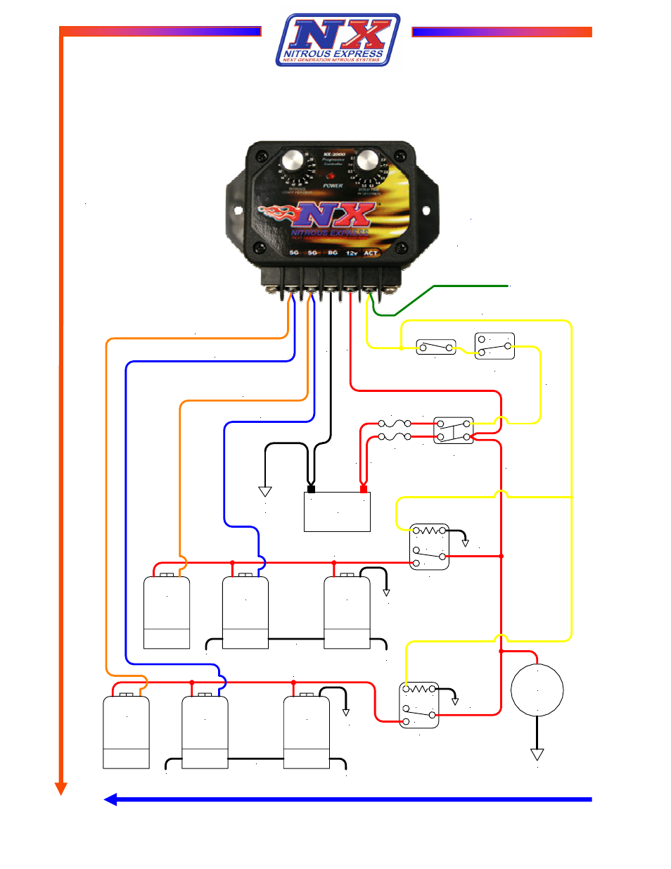
Multiple Nitrous-Fuel Solenoid Installation
6.1—
Hold and Wait Style Progressive Timer
+
-
Battery
Chassis/Engine
Ground
Nitrous Arming
Switch
DPST
Fuse, 10 Amp
Fuse, 30 or
40 Amp
30
87
87A
85
86
+
-
Nitrous
Fuel Pump
Ground
16 GA Black
Safety
Solenoid
Nitrous
Solenoid
Fuel
Solenoid
To
Nitrous
Bottle
To Engine
40 Amp Relay
Launch Switch
and/or
Line Lock
Throttle Switch
Ground
20 GA Black
Ground
16 GA Black
Solenoid +12V Supply, 14GA Red
Nitrous Feed Line
Nitrous Solenoid Ground, 14GA Blue
Fuel Solenoid Ground, 16GA Orange
C
NO
NC
B
att
ery G
roun
d,
14G
A
B
lac
k
Safety Relay Activation, 20GA Yellow
20 GA
Red
14 GA
Red
+1
2V
S
w
itc
he
d, 2
0 G
A
R
ed
20 G
A
R
ed
14 G
A
R
ed
14 G
A
R
ed
A
cti
vat
ion +
12V
, 20G
A
Y
ell
ow
30
87
87A
85
86
40 Amp Relay
Ground
20 GA Black
Safety
Solenoid
Nitrous
Solenoid
Fuel
Solenoid
To Nitrous Bottle
To Engine
Solenoid +12V Supply, 14GA Red
Nitrous Feed Line
Ground
16 GA Black
Nitrous Solenoid Ground, 14GA Blue
Fuel Solenoid Ground, 16GA Orange
Note - The Red LED lamp should
be on steady with Arming Switch
ON and the Activation Signal OFF.
LED Lamp will blink when +12V is
applied to the Activation Terminal.
Note - The activation terminal has an
integrated resistor to Ground. This is to
insure that the Timing Retard Inputs of
popular Ignitions are OFF when the
Controller is NOT activated.
Timing Retard Activation
Connect to Timing
Retard Module
Activation Input