Nitrous Express MASTER FLO-CHECK PRO (15529) User Manual
Nitrous Express For the car
MASTER FLO-CHECK
PN 15519
MASTER FLO-CHECK PRO
PN 15529
The Flo-Check is used to establish a base line
tune-up for your NX system. Nothing more. After a
clean, full power pass, the final tune-up will be deter-
mined by spark plug readings (see “Power Tuning
Tips” in your nitrous system instructions).
The Master Flo-Check is easy to use and a reliable
way to establish the flowing fuel pressure of your NX
nitrous system:
1. By consulting the jet chart on the reverse side,
select the proper jet required to flow the HP set-
ting on your NX system.
2. Plate systems only. The fuel pressure must be
measured before the fuel enters the solenoid.
Select the proper adaptors, included in the Flo-
Check kit, to connect the supplied pressure gauge
to the proper location on the N2O system fuel
supply side.
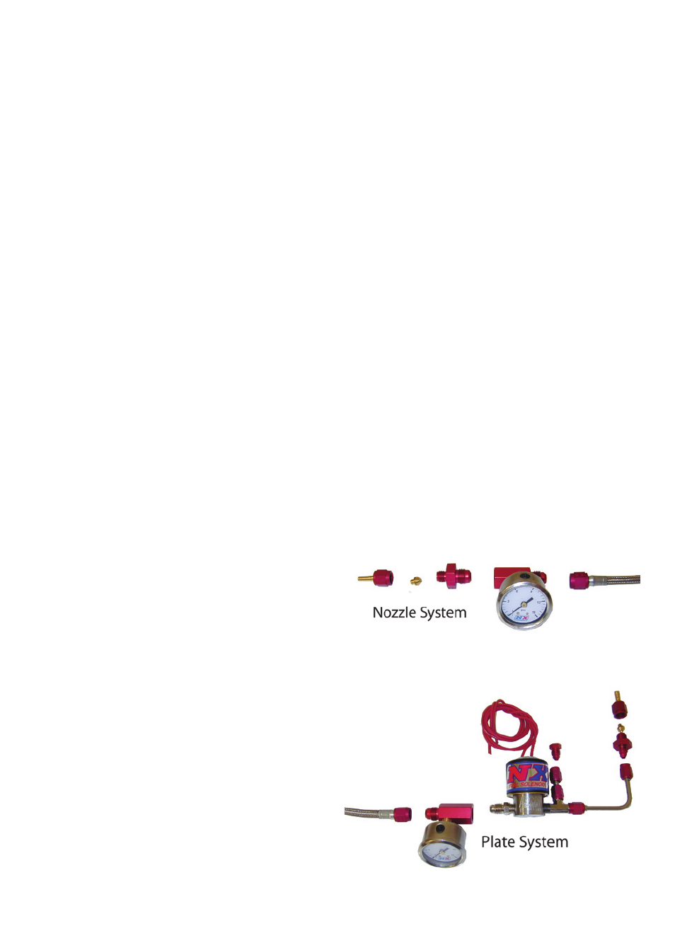
3. Nozzle systems only. On either single or double
solenoid nozzle systems the fuel pressure may
be checked anywhere in the fuel system after the
regulator and before the fuel solenoid. Select the
proper adaptors, included in the Flo-Check kit, to
connect the supplied pressure gauge to the proper
location on the N2O system fuel supply side.
4. PN 15529 only. The 6” certified calibration gauge
is designed to operate in the up-right position
only, do not lay flat when checking the fuel pres-
sure! The gauge should be help up right at about
the same height as the fuel solenoid, varying the
height will change the fuel pressure readings.
5. PN 15519 only. Install the supplied fuel pressure
gauge directly on the blue adaptor manifold.
6. Plate systems only. Use the supplied fitting
to secure the jet to the 3/16 stainless steel fuel
jumper line that connects the solenoid to the N2O
plate. Note: On Gemini twin series plates use the
supplied D-3 plug to block one side of the fuel
plumbing.
7. Nozzle systems only. Use the supplied adaptors
to connect the jumper line that leads to either fuel
solenoid to the Flo-Check manifold. Using the
specially modified jet-fitting, insert the proper
flow jet, and install the jet retaining cap.
8. Before beginning the flowing adjustments discon-
nect the power from the N2O solenoid (on plate
systems) to avoid accidental nitrous discharge
into the intake tract and avoid electro-magnet over
heating. On nozzle systems turn the master arm
switch to the “Off” position.
9. Attach a small diameter hose to the jet fitting to
carry the fuel to a safe, approved storage container
away from hot engine parts.
10. Use extreme caution when using this device. Gas-
oline is very flammable and could cause serious
injury or death if ignited.
11. When all cautions have been observed turn the
fuel pump on and using the pressure regulator,
adjust the fuel pressure to the proper level. Note:
Plate systems require the fuel solenoid to be acti-
vated while the fuel pressure is being adjusted.
Your particular application may require the fuel
pressure to be substantially lower than indicated
on the attached chart. If you plug readings indi-
cate an over rich condition lower the fuel pres-
sure in .10 lb increments until the plug readings
improve
Note: The nitrous and fuel solenoids are rated only
for intermittent duty. Do not engage either solenoid
for more than 20 continuous seconds. Solenoids that
have “burned or scorched” electro-magnets will not
be replaced under warranty.