Place picture of rad mounted bracket in this space – Flex-a-Lite 52181C3 Corvette Radiator & Fan Kits User Manual
Page 3
Gently slide “T-bolts” of “L”-bracket sub-assemblies down channel of radiator end tank. Use the channel
3.
second from front as a starting point.
(see Detail K) Do not tighten up “T-bolts” at this time. Insert 1-3/4”
bolt through hole in radiator support, then loosely place fender washer and 5/16” locknut onto bolt threads.
Once “L”-bracket sub-assemblies have been positioned on both sides of radiator, adjust alignment as
necessary and tighten all hardware securing radiator to radiator support.
Note: Make sure that the top foam
strips of radiator are being compressed when tightening bracket hardware.
(see Detail K)
Installation instructions continued from previous page
Rev. 07-30-12 99181 Page 3 of 6
(Detail J)
L-bracket sub-assembly.
“Exploded view”
(Detail K)
Top view of L-bracket assembly on
passenger’s side secured to Radiator support.
Note: If your vehicle is equipped with an automatic transmission, an aftermarket transmission
cooler kit should be installed during new radiator installation.
Installation of Radiator and Fan Kits #52180
C
3 & #52181C3
Find the provided pressure sensitive foam strips (4ea.) and apply to radiator tanks at top and bottom of
machined tank surfaces where radiator will be making contact with radiator support. The foam strips will
help to isolate vibration between radiator tanks and radiator support.
(see Detail H)
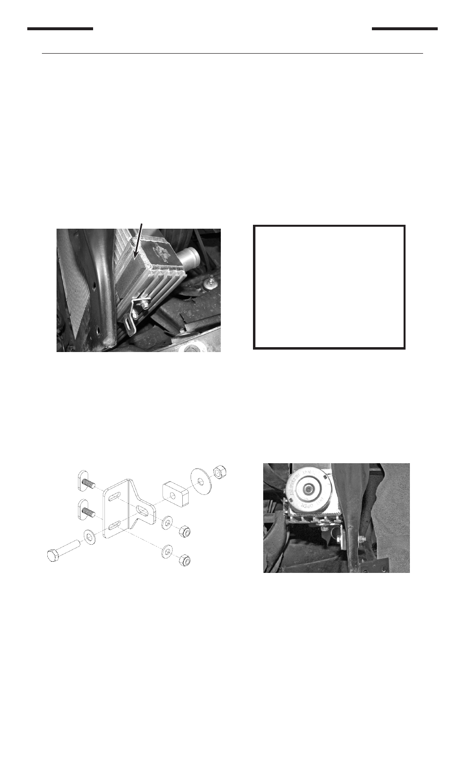
Note: When installing Rad. / Fan kit #52181C3 into vehicle, replacing a OEM 27-1/2” core, mount supplied
optional bracket to lower right hand corner as shown. This bracket is needed to reach the passenger side
bottom cradle.
(see Detail I) Adjust as needed to mount securely.
Carefully lower the radiator / fan assembly into position nesting the protruding studs along the bottom of the
1.
radiator onto the lower brackets and into the grommets cradled within them.
Assemble the “L”-bracket sub-assemblies (2ea.).
2.
(see Detail J): Insert “T-bolts” (2ea. per bracket) through
slots then loosely place ¼” washers and locknuts on bolt threads. Place 5/16” washer onto 1-3/4” long bolt
then insert bolt through bracket. On other side of bracket slide rubber spacer onto bolt.
Re-secure the pulley to the water pump, then reinstall fan belt. Reinstallation of pulley to water pump
4.
flange will require shorter replacement bolts.
After being tightened, there should be no less than ¼”
of clearance to the water pump. If they are too close, they may cause severe damage to the water
pump upon start-up.
Connect the upper and lower radiator hoses to the new radiator. Make sure they are properly clamped to
5.
the inlet and outlet tubes.
Install the provided pipe-nipple for the coolant overflow hose into filler neck of the radiator. Attach & secure
6.
the small overflow hose onto previously installed pipe-nipple.
Fill radiator / cooling system with vehicle manufacturer recommended coolant until coolant level stabilizes
7.
then attach cap formerly detached from removed radiator. Continue filling cooling system through
expansion tank until “Cold Fill Level” is reached. Replace expansion tank cap and check for leaks before
proceeding.
Note: BE SURE that all moving parts of the engine and electric fan (where applicable) are clear of
each other before proceeding!!
(Detail H)
Location of foam strip.
Place foam strip at all four corners.
(Detail I)
Place picture
of rad mounted
bracket in this
space