Wiring instructions – Flex-a-Lite M350 Monster Fan Class V-VIII User Manual
Page 2
WIRING INSTRUCTIONS
A. G
ENERAL
N
OTES
: This section contains complete instructions for basic installation, wiring for air-conditioned
vehicles, and wiring the optional manual control switch. Please review the section thoroughly before you begin.
NOTE: Failure to follow these instructions may cause premature fan failure or an unsafe installation. As neces-
sary connections are made, insure that there is ample slack wire to allow for engine movement. Also insure that
all wires are clear of moving parts (belts, pulleys, etc.) and high temperature parts (exhaust system components).
The M350 wiring package includes ring connectors, three-way connectors, butt connectors, tie wraps and wire
end caps. Use the tie wraps to secure wires properly and the wire end caps to cap wires protruding from the
control module which are unnecessary in your specific application. The remaining connectors should be used as
appropriate to make the connections specified below.
B. WIRING THE FAN UNIT:
1. There should be four 10GA wires leading from the fan. Two Red, positive (+) leads, and two Black, Nega-
tive(-) leads. The Red leads need to be wired to a Positive 12V DC source, such as a battery terminal or
remote battery terminal, capable of handling a total of 50 amps. Each lead should have a fuse holder placed in line
with the Positive lead. Wrap the terminals with electrical tape to avoid making contact with a ground.
C. W
IRING
T
HE
E
LECTRICAL
C
ONTROL
M
ODULE
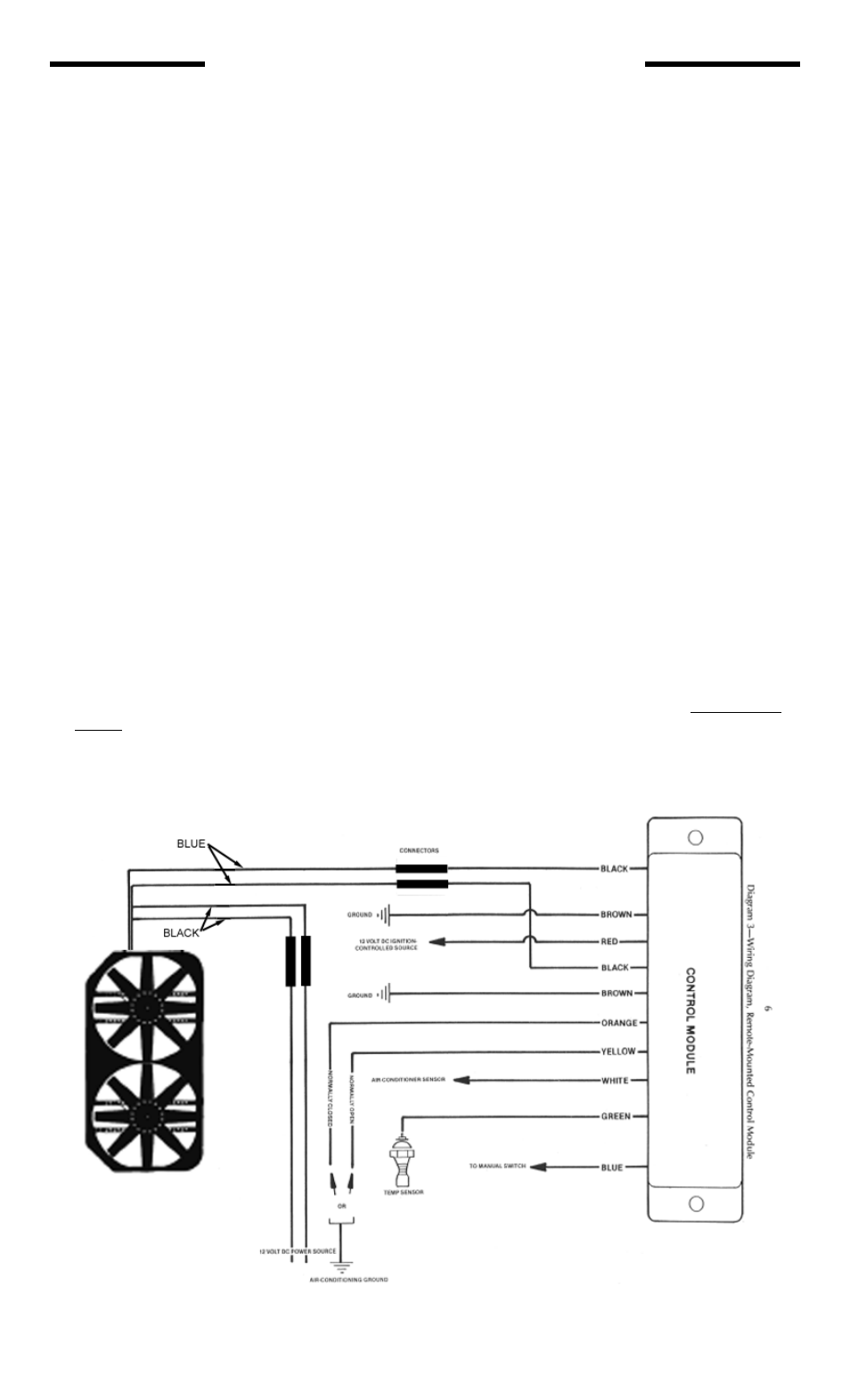
: (Refer to Diagram 3.)
1. Black Wires (2)
Connect these wires with connectors which mate with the two black wires from the fan. If extra wire must be
used, be sure it is tie-wrapped.
2. Brown Wires (2)
Connect to a good single grounding point such as negative terminal of battery, engine, or frame rail.
NOTE: These wires carry the full current of the motors. For proper operation, a good grounding
point is imperative.
3. Red Wire (1)
Connect to a 12 volt DC ignition-controlled power source.
NOTE: The connecting point for this wire will not be the same source you used for the red wires
protruding from the shroud. The red wire from the control module must connect to an ignition-con-
trolled source, and such sources typically cannot provide the amperage necessary to support fan
operation.
4. Green Wire (1)
Connect to the cooling temperature sensor. This is a ground signal switch.
Diagram 3 - Wiring Diagram
Remote-Mounted
Control Module
rev. 06-22-05 part no. 99993M Page 2 of 3