Installation (continued from page 1), Wiring the variable speed control – Flex-a-Lite 262 Dual Electric Fan User Manual
Page 2
INSTALLATION (CONTINUED FROM PAGE 1)
4. Place the fan into the vehicle by placing the tabs on the bottom of the shroud into the
factory slots at the bottom of the radiator. NOTE: View old shroud tabs for reference.
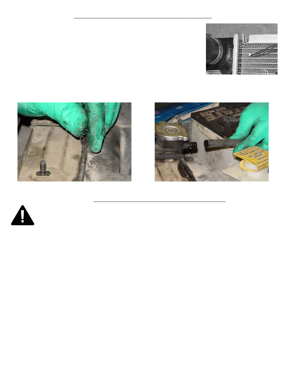
5. Pull the new shroud to the radiator and place the 2 small clips from the factory
shroud to the top edge of the new shroud to hold in place. see detail 5.
6. Utilizing the 4 bolts from the factory shroud and the factory mounting holes, bolt the
new fan assembly in place.
7. Secure lower electrical harness so as not to be loose
8. Install the windshield wash reservoir to the new shroud in the same way as the
coolant overflow bottle. NOTE: See step #2 of this section for reference.
9. Replace coolant overflow bottle hose to radiator. see detail 6.
10. Attach the upper “inlet” hose to the radiator. Be sure the the drain plug is closed and refill the radiator with coolant.
11. Reinstall the battery cable from the primary battery to the secondary battery using a 10mm socket.
WIRING THE VARIABLE SPEED CONTROL
98262 page 2 of 4 rev . 03-24-08
DETAIL #4
DETAIL #5
DETAIL #6
FOLLOW THESE INSTRUCTIONS CAREFULLY TO AVOID DAMAGING THE CONTROL
UNIT, FAN MOTORS, AND YOUR VEHICLE! WHEN CRIMPING WIRES, ALWAYS USE A
QUALITY CRIMPING TOOL (DO NOT USE PLIERS OR OTHER DEVICES).
1. Find the thick red and black wire bundles in the wiring kit. Use the yellow butt connectors to crimp the red wire to
the short red wire on the Variable Speed Control (VSC), and the black wire to the short black wire on the VSC (see
wiring diagrams below).
2. Determine the length needed to connect the red and black power leads to the battery terminals on the primary battery
on the drivers side and trim appropriately. Crimp a large yellow ring connector to the end of the black wire and connect
to the negative (-) battery terminal but DO NOT connect the red wire yet.
3. Find a convenient place to mount the circuit breaker between the VSC and the positive (+) battery terminal and use
the 2 screws provided to mount it securely. Cut the red wire at the point where you mounted the circuit breaker. Find the
red boot for the circuit breaker and lay it on the breaker as shown in detail #7. Crimp a small yellow ring connector to
the ends of the wires and connect them to the circuit breaker. NOTE: BE SURE TO CONNECT THE END COM-
ING FROM THE BATTERY POSITIVE (+) TERMINAL TO THE “BAT” TERMINAL ON THE CIRCUIT
BREAKER (COPPER COLORED). Once both positive (+) wires are connected to the circuit breaker, fold the top of
the boot over and press to fit. This will help insulate the circuit breaker from arcing. see detail #7.
4. Crimp a large ring connector to the positive (+) battery end of the power lead and connect it to the battery terminal.
5. Locate power distribution box (fuse box). Find a circuit that is “hot” when the key is in the “ON” position. NOTE:
DO NOT use the DRL or brake/ taillight fuse! Attach the included fuse tap to the fuse. Attach a pink female connec-
tor to the thin red wire included and attach to the fuse tap. Trim the wire so that it will reach the VSC. Attach pink
female connector to the other end of the wire and connect it to terminal #9 on the VSC.