Flex-a-Lite 31143 Illuminated 3-Way Switch Kit User Manual
Flex-a-Lite For the car
1
98143 Rev. 01-22-14
1. Determine mounting position for the switch. Look for
a flat section of panel that is easily accessible from the
driver’s seat to activate.
2. Check to make sure there are no wires or
electronics directly behind this area. You will also need
a minimum depth clearance of 1-3/4” to clear the switch
body and the wires to attach.
The Flex-a-lite illuminated 3-way switch allows for
in-vehicle control of your fan. By directly connected
to the pins located on the controller, you can shut
your fan off during water crossings, or keep the fan
running at 100% power for towing up steep roads.
3. Mark off a rectangular hole 1-1/2” Tall x 7/8” Wide with
masking tape where you plan to mount the switch. If
you can remove this panel from the vehicle, cutting this
hole will be easier. Drill the corners of the marked
rectangle and remove the remaining material with a
small cutting blade and a file. Make sure the hole is clear
of any loose material or sharp filings.
7. Find a suitable location in the firewall of the vehicle
to pass these 4 wires through. If drilling, make sure
to use a grommet on the firewall to prevent abrasive
damage to the wire. Leave enough wire inside the
vehicle to easily reach the switch mounting hole.
8. Cut the green and orange wires to length for
reaching the flag terminals located on the fan
controller. Strip the orange and green wires
and crimp an insulated flag terminal to each.
Attach to associated controller terminals.
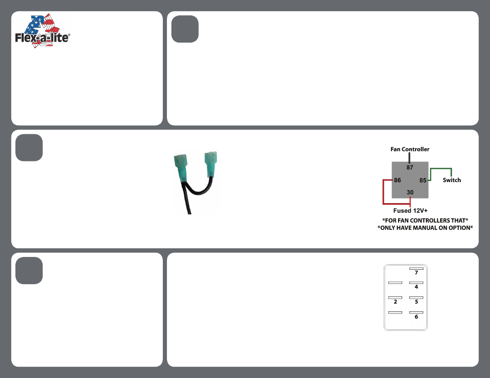
NOTE: On Flex-A-Lite fan controllers which only have the
option for manual on, a relay needs to be wired between
the switch wire and controller as shown in the diagram to
the right.
9. Cut the red and black wires to length to reach the
battery. Strip each wire and crimp on the included ring
terminals. Connect the red wire to the positive (+)
battery terminal and the black wire to the negative (-)
battery terminal. NOTE: Depending on your install appli-
cation, the red wire can also be connected to an ignition
controlled 12V source. Do not tap into headlight wires or
windshield wipers!
10. Inside the vehicle, connect the flag terminals on the
black wire to pins 2 and 5 on the switch, and the red wire
to pin 7. (Fig. 2)
11. Turn your vehicle ignition to the on position. Plug in
the orange or green wire into pin 4 on the switch. Toggle
the switch up towards pin 7; if this does not turn the fan on
remove and replace with the other color wire.
Connect the remaining wire to pin 6.
12. Turn your vehicle ignition off. Make sure all wires are
securely mounted and press the switch until it sits flush
and locks into the vehicle panel.
#31143 Illuminated 3-Way Switch Kit
Create Switch Mount Location
4. Cut a small (~2”) segment off of included black wire.
Strip both ends of the wire and one end of the wire that
was cut from. Twist One end of the small segment to
the long wire, and crimp 2 of the included insulated flag
terminals to the exposed end. (Fig. 1)
5. Strip one end on both the orange and green wires.
Crimp an insulated flag terminal to each.
6. Strip one end of the included red wire. Crimp an
insulated flag terminal to the wire.
2
Prep & Run Wires
3
Install & Test
Fig. 1
Fig. 2
Register your product for warranty at
http://automotive.flex-a-lite.com/warranty-registration/
Enjoy your Flex-a-lite performance cooling product!
If you need further assistance, please contact tech services
at 253-922-2700 M-F 8:00am-5:00pm PST.