Wiring instructions continued – Flex-a-Lite 432 Lo-Profile S-blade Fan User Manual
Page 3
WIRING INSTRUCTIONS CONTINUED
Step 6: Use the small diameter red wire (18 AWG) to connect the “+” terminal on the control module to a posi-
tive power source. NOTE: Attaching this wire to an ignition-controlled source will shut off the fan when
the engine is turned off. Attach this wire to an uninterrupted (always hot) power source to allow the fan
to continue running after the engine is shut off. Use the blue female connector and fuse taps (included) if
necessary.
Step 7: (Optional) For air conditioning control (if desired) connect the “C” terminal on the control module to the
positive wire that triggers the A/C compressor using the small diameter green (14 AWG) wire. Using a voltme-
ter, determine which wire coming from the compressor is the positive trigger wire. Use the blue “tap-in con-
nector” (included) to tap into this wire and send a signal to the fan control module. The fan will cycle on and off
with the A/C clutch when the A/C is turned on.
Step 8: (Optional) For manual switch operation, use Flex-a-lite part #31148. Connect the switch as shown on
the wiring diagram (previous page). Connect the “M” terminal on the control module to the “1” terminal on the
switch. Connect the “2” terminal on the switch to a positive 12v power source. Connect terminal “3” on the
switch to a good ground (for switch illumination). NOTE: To prevent thermostatic activation (if only manu-
al switch operation is desired), omit the lead to the “+” terminal of the control box. “B”, “G”, “M+” and
“M-” must remain connected. If not using a Flex-a-lite manual switch, do not connect a ground wire to
the switch!
Use the zip ties provided to secure the wires and prevent them from interfering with fan blades, belts, and pul-
leys in the engine compartment. Reconnect the battery and insert the fuse provided.
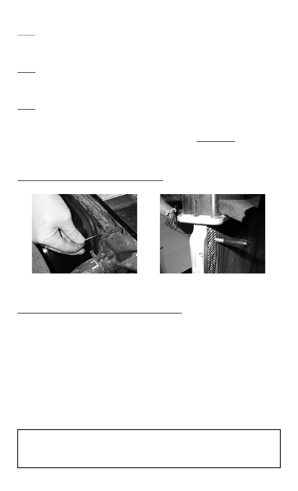
Step 9: Insert the temperature probe into the radiator fins
Install temp. probe near inlet hose...
then replace the insulator cap.
Locate the inlet hose from the engine to the radiator. Remove the black insulator cap and insert the temp.
probe through the radiator fins near the inlet hose. Reinstall the black insulator cap.
Step 10: Adjust the temperature control knob on the control box
If you disconnected any hoses or drained coolant to install the fan, reconnect the hoses and refill the radiator.
Press the control knob (included in wiring kit) onto the control box shaft. Turn the knob clockwise until it stops.
Start the engine and allow it to idle. Using a digital thermometer (positioned near the inlet hose) or the vehi-
cle’s temperature gauge, monitor the temperature. When the coolant temp. is slightly above normal (or desired
temp.), turn the knob counter-clockwise just until the fan turns on. From now on, the fan should activate at this
temperature setting. Adjust as necessary to maintain desired temperature.
The Flex-a-lite Limited Warranty
Flex-a-lite Consolidated, 7213-45th St. Ct. E. Fife, WA 98424, Telephone No. 253-922-2700, warrants to the original purchasing user, that all Flex-a-lite products to be free of
defects in material and workmanship for a period of 365 days (1 year) from date of purchase. Flex-a-lite products failing within 365 days (1 year) from date of purchase may
be returned to the factory through the point of purchase, transportation charges prepaid. If, on inspection, cause of failure is determined to be defective material or workman-
ship and not by misuse, accidental or improper installation, Flex-a-lite will replace the fan free of charge, transportation prepaid. Flex-a-lite will not be liable for incidental,
progressive or consequential damages. Some states do not allow the exclusion or limitation of incidental or consequential damages, so the above limitation or exclusion may
not apply to you. This warranty gives you specific legal rights and you may have other rights, which vary from state to state.
The Flex-a-lite warranty is in compliance with the Magnuson-Moss Warranty Act of 1975.
Rev. 07-13-10 99813 Page 3 of 4