Flex-a-Lite 18024 24 Volt, Universal Fit User Manual
Page 2
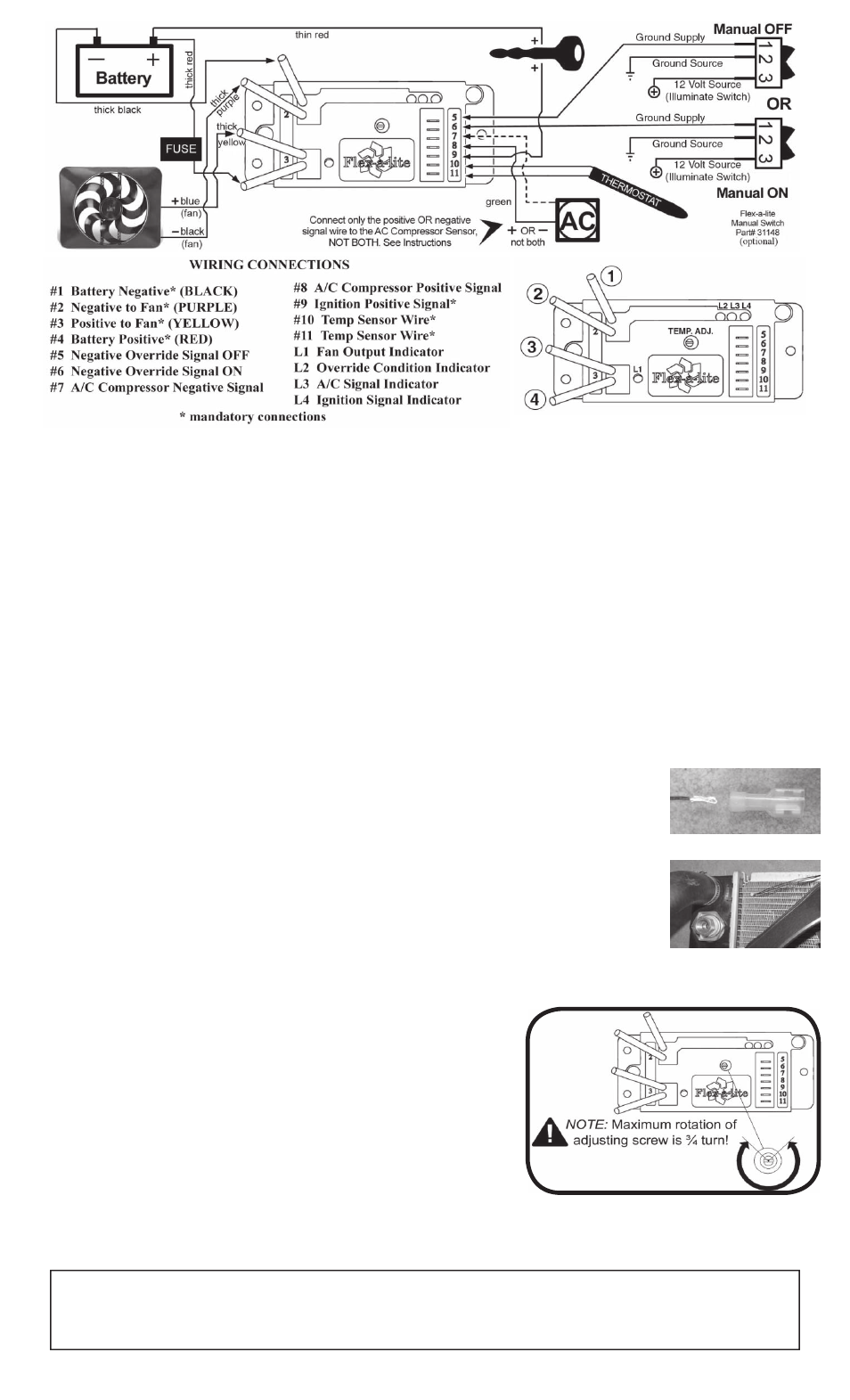
1. Turn ignition on. After 5-6 seconds, LED #4 should light up. If not,
check to make sure that you have 12 Volts at terminal #9 on VSC.
The delay is to allow starter to start the vehicle without the fans draw-
ing any power.
2. With your engine running, engage the A/C. Your fans should come on
and cycle with the A/C clutch. LED's #1, 3 and 4 should be lit when
fans are running. If they do not turn on, verify that the A/C clutch
is engaged and make sure that you have the appropriate wire con-
nected to correct terminal on the VSC. Shut off A/C and let engine
continue to idle until you reach operating temperature.
3. Verify that operating temperature has been reached by feeling upper radiator hose. Hot water should be flowing
through hose into the radiator. Adjust the screw on the VSC counterclockwise for a cooler setting or clockwise for
a warmer setting. Once desired temperature is set, let engine continue to idle to make sure the fans will cycle to
maintain desired temperature. When fans are running, LED's #1 and 4 should be lit.
Initial Set-up and Adjustment
1. Find the thick red and black wire in the kit. Determine the length needed to connect the red and black power leads
on the VSC to the battery terminals and trim appropriately. Crimp a large yellow ring connector to the end of the
black wire and connect to the negative (-) battery terminal. Connect the other end to the black wire on the VSC
with a large butt connector (yellow sleeve).
2. Locate the fuse holder. DO NOT INSTALL THE FUSE UNTIL ALL THE WIRING IS COMPLETE. Attach a large
ring connector to one end and a yellow insulated butt connector to the other end of the fuse holder. Attach the ring
connector to the positive (+) terminal of the battery and connect the other end to the thick red wire found in the kit.
Determine the length of wire needed to reach from the fuse holder to the red wire on the VSC and trim appropri-
ately. Use a yellow insulated butt connector to connect this wire to the red wire on the VSC. You may use the 2
small screws to mount the fuse holder if desired.
3. Find a circuit that is "hot," preferably in a fuse box, when the key is in the "ON" position. Nothing that is directly
linked to the ignition, computer system, or transmission. Attach the included fuse tap to fuse. Attach a pink fe-
male connector to one end of the thin red wire (included) and connect to fuse tap. Determine length of wire needed
to reach VSC and trim to appropriate length. Attach a pink female connector to the end of the wire and connect to
terminal #9 on VSC.
4. Locate wires going to the A/C compressor. Determine length of supplied thin green wire needed to reach VSC from
the A/C compressor and trim to length. Determine which wire is ground and which wire is positive by using a volt
meter.
If the A/C compressor is activated by a positive (+) signal;
• Connect the positive wire to the supplied thin green wire by use of a piggyback connector. Attach a pink female
connector to other end of thin green wire then attach connector to terminal #8 on VSC.
If the A/C compressor is activated by a negative (-) signal;
• Connect the negative wire to the supplied thin green wire by use of a piggyback connec-
tor. Attach a pink female connector to other end of thin green wire then attach connector
to terminal #7 on VSC.
5. Locate temperature probe. Gently push the probe through fins in radiator as close to the
upper radiator hose as possible with ¼"-½" of the probe protruding out of the front of the
core. Install the rubber cap on the front side of the probe (if possible). This will give the
VSC the most accurate engine temperature reading. Determine length of wire needed to
reach VSC.
IMPORTANT: Strip the insulation on the temperature probe wires back about
1" and fold the wire on itself to effectively double the thickness of the wire before connect-
ing spade connectors. Then attach these wires to terminals #10 & #11. Both wires need
to be connected, but it doesn't matter which wire goes to each terminal.
6. If manual switches (Flex-a-lite #31148) have been purchased, attach them as following.
To override engine temperature to turn fans off, connect the switch to terminal #5 on VSC
to send a ground signal. To override engine temperature to turn fans on, connect the switch to terminal #6 on the
VSC so that a ground signal is sent.
The Flex-a-lite Limited Warranty
Flex-a-lite Consolidated, 7213-45th St. Ct. E. Fife, WA 98424, Telephone No. 253-922-2700, warrants to the original purchasing user, that all Flex-a-lite products to be free of defects in material and work-
manship for a period of 365 days (1 year) from date of purchase. Flex-a-lite products failing within 365 days (1 year) from date of purchase may be returned to the factory through the point of purchase,
transportation charges prepaid. If, on inspection, cause of failure is determined to be defective material or workmanship and not by misuse, accidental or improper installation, Flex-a-lite will replace the fan
free of charge, transportation prepaid. Flex-a-lite will not be liable for incidental, progressive or consequential damages. Some states do not allow the exclusion or limitation of incidental or consequential
damages, so the above limitation or exclusion may not apply to you. This warranty gives you specific legal rights and you may have other rights, which vary from state to state. The Flex-a-lite warranty is
in compliance with the Magnuson-Moss Warranty Act of 1975.
Rev. 07-20-11 Part #98024 Page 2 of 2