CMP PXSS2K-REX User Manual
Page 2
INSTALLATION INSTRUCTIONS FOR CMP CABLE GLAND TYPE PXSS2K-REX
DUBAI
• HOUSTON • NEWCASTLE • SINGAPORE • SHANGHAI • PUSAN • PERTH
DUBAI
• HOUSTON • NEWCASTLE • SINGAPORE • SHANGHAI • PUSAN • PERTH
www.cmp-products.com
www.cmp-products.com
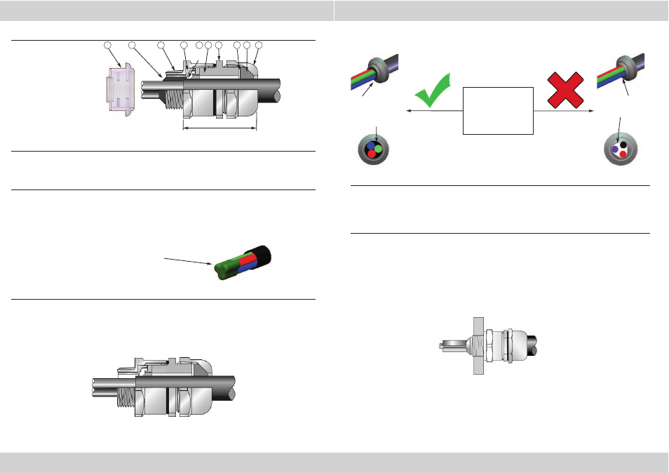
CABLE GLAND COMPONENTS
1. Separate the gland components by removing the main item (6) and outer seal nut assembly (7, 8, 9).
Slacken the outer seal nut slightly to relax the seal and pass the main item/outer seal nut assembly
over the cable, nut end first.
Prepare the cable by stripping back the outer sheath to suit the equipment.
2. Remove any bedding or fillers from around the cable cores. If the cable cores have screens, these
should be unravelled and then twisted together to form a single core.
This single core and/or any drain wires present should be sleeved with some heat shrink tubing.
3. Feed the cable carefully into the entry item (2) through the resin dam (4). Reassemble the gland
and adjust the position of the cable if necessary to that the outer sheath just protrudes through the
resin dam. (Use length ‘L’ as a guide for positioning the cable). Tighten the outer seal nut enough to
secure the gland.
N.B. If the outer sheath is too large to pass through the spacer then wrap some electrical tape around
the cores at the point they pass through the resin dam.
PLEASE READ ALL INSTRUCTIONS CAREFULLY BEFORE BEGINNING THE INSTALLATION
4. Refer to ‘RapidEx Resin’ assembly instructions to fill the connector Compound Tube
with the required amount of resin. The resin should not be mixed or applied at
temperatures below 5°C (40°F).
5. Once the resin has cured remove the thread shield, loosen the outer seal nut and remove the
main item (6) and outer seal nut assembly (7,8,9) from the entry item (2). Fit the entry item into
the equipment.
6. Re-install the cable assembly into the entry item and fully tighten the main item (6) onto the
entry item (2). Tighten the outer seal nut (9) until it comes to an effective stop. This will occur
when :-
A) The outer seal nut (9) has clearly engaged the cable and cannot be further tightened
without the use of excessive force by the installer.
B) The outer seal nut (9) is metal to metal with the main item (6).
6
3
4
2
1. Resin
2. Entry Component “A”
3. Compound Tube
4. Resin Dam
5. Spacer
6. Main Item
7. Skid Washer
8. Outer Seal
9. Outer Seal Nut
10. Thread Shield
8
7
9
Resin Dam with
good contact
with cable sheath
or electrical tape.
Resin Dam with
poor contact
with cable
cores.
Ensure Resin Dam is
in position in the
gland and making a
good seal against the
inner sheath.
Do not disassemble the gland to inspect the Resin Dam, diagrams
are for representation.
Electrical tape MUST be wrapped around the tips of the
cable cores. This is to ensure the cable cores are
together and also to cover any sharp edges that could
potentially tear the Resin Dam during installation.
10
Resin
Dam
1
5
‘L’