CMP PXRC-REX User Manual
Cable gland, Cable gland type pxrc-rex type pxrc-rex
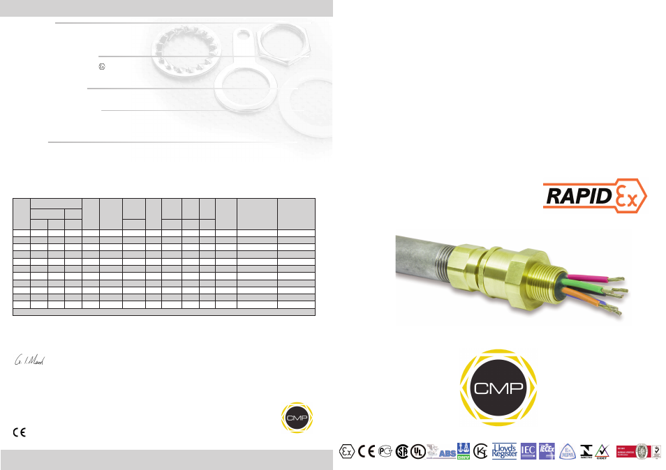
INSTALLATION INSTRUCTIONS FOR
CMP CONDUIT GLAND TYPE PXRC-REX
BARRIER CABLE GLAND FOR USE IN HAZARDOUS AREAS WITH BRAID, UNARMOURED CABLE OR
INDIVIDUAL CORES HOUSED IN CONDUIT.
INCORPORATING EC DECLARATION OF CONFORMITY TO DIRECTIVE 94/9/EC
CM
P
Do
cu
m
en
tN
o.
FI
41
5
Is
su
e
5
01
/1
3
0518
Glasshouse Street • St. Peters • Newcastle upon Tyne • NE6 1BS
Tel: +44 191 265 7411 • Fax: +44 191 265 0581
E-Mail: [email protected] • Web: www.cmp-products.com
Notified Body: Sira Certification Service, Rake Lane, Chester CH4 9JN, England.
I, the undersigned, hereby declare that the equipment referred to herein conforms to the requirements of the ATEX Directive 94/9/EC and the
following standards:-
EN60079-0:2009, EN60079-1:2007, EN60079-7:2007, BS 6121:1989, EN50262:1998 (Amd 2011), EN61241-0:2004, EN61241-1:2004
Dr Geof Mood - Technical Director - (Authorised Person)
DUBAI
• HOUSTON • NEWCASTLE • SINGAPORE • SHANGHAI • PUSAN • PERTH
www.cmp-products.com
Ca
bl
e
Gl
an
d
Se
le
ct
io
n
Ta
bl
e
Logo’s shown for illustration purposes only. Please check certification for details
CABLE GLAND
CABLE GLAND
TYPE PXRC-REX
TYPE PXRC-REX
Cable
Gland
Size
Available Entry Threads
Minimum
Thread
Length
Standard
Female
Connection
Thread
Diameter
Over
Conductors
Number
Of
Cores
Overall
Cable
Diameter
Across
Flats
Across
Corners
Nominal
Protrusion
Length
Ordering Reference
(Brass Metric M X F)*
Cale Gland Weight
(Kgs)
Standard
Option
Metric
NPT
NPT
Max
Max
Max
Max
20
M20
1/2”
3/4”
15.0
1/2”
12.6
21
13.9
27.0
29.7
24.0
20PXRCREX1RA031
0.100
25
M25
3/4”
1”
15.0
3/4”
17.5
38
19.9
36.0
39.6
26.0
25PXRCREX1RA032
0.250
32
M32
1”
1-1/4”
15.0
1”
23.6
59
26.2
41.0
45.1
27.0
32PXRCREX1RA033
0.460
40
M40
1-1/4”
1-1/2”
15.0
1-1/4”
30.0
89
32.3
50.0
55.0
28.0
40PXRCREX1RA034
0.615
50S
M50
1-1/2”
2”
15.0
1-1/2”
36.6
115
38.9
55.0
60.5
29.0
50SPXRCREX1RA035
0.710
50
M50
2”
2-1/2”
15.0
2”
41.0
115
44.2
60.0
66.0
30.0
50PXRCREX1RA036
0.700
63S
M63
2”
2-1/2”
15.0
2”
47.9
140
50.0
70.0
77.0
30.0
63SPXRCREX1RA036
0.850
63
M63
2-1/2”
3”
15.0
2-1/2”
53.7
140
58.0
75.0
82.5
30.0
63PXRCREX1RA037
0.820
75S
M75
2-1/2”
3”
15.0
2-1/2”
59.9
140
62.4
79.0
86.9
32.0
75SPXRCREX1RA037
1.100
75
M75
3”
3-1/2”
15.0
3”
64.3
140
68.1
84.0
92.4
32.0
75PXRCREX1RA038
1.090
90
M90
3”
3-1/2””
15.0
3-1/2”
75.3
140
80.1
108.0
118.8
44.0
90PXRCREX1RA038
1.500
All dimensions in millimetres unless otherwise stated
* Please specify MALE & FEMALE threads requires when ordering
TECHNICAL DATA
CABLE GLAND TYPE
: PXRC-REX
INGRESS PROTECTION
: IP66 minimum
PROCESS CONTROL SYSTEM
: BS EN ISO 9001
: ISO/IEC 80079-34:2011
HAZARDOUS AREA CLASSIFICATION
ATEX CERTIFICATION No
: SIRA 06ATEX1097X
ATEX CERTIFICATION CODE
:
II 2 GD Ex d IIC / Ex e II / Ex tD A21 IP66
IEC Ex CERTIFICATION No
: IEC Ex SIR.06.0044X
IEC Ex CERTIFICATION CODE
: Ex d IIC / Ex e II / Ex tD A21 IP66
INSTALLATION INSTRUCTIONS
Installation should only be performed by a competent person using the correct tools. Spanners should be used for tightening. Read all instructions
before beginning installation.
SPECIAL CONDITIONS FOR SAFE USE
1. The cable gland ranges shall only be used where the temperature, at the point of entry, is in the following ranges:
-60°C to +85°C.
2. The entry component threads may need additional sealing to maintain the ingress protection ratings as applicable to the associated equipment to
which it is attached.
ACCESSORIES
The following accessories are available from CMP Products, as optional extras, to assist with fixing, sealing and earthing :-
Locknut | Earth Tag | Serrated Washer | Entry Thread (I.P.) Sealing Washer | Shroud