CMP PXSS2K-REX User Manual
Cable gland, Cable gland type type pxss2k-rex pxss2k-rex
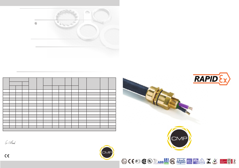
INSTALLATION INSTRUCTIONS FOR
CMP CABLE GLAND TYPE PXSS2K-REX
FOR TERMINATION OF UNARMOURED, BRAIDED CABLES AND EXTRA HARD CORD USEAGE CABLES.
FOR USE IN HAZARDOUS LOCATIONS.
INCORPORATING EC DECLARATION OF CONFORMITY TO DIRECTIVE 94/9/EC
CM
P
Do
cu
m
en
tN
o.
FI
40
3
Is
su
e
4
01
/1
3
0518
Glasshouse Street • St. Peters • Newcastle upon Tyne • NE6 1BS
Tel: +44 191 265 7411 • Fax: +44 191 265 0581
E-Mail: [email protected] • Web: www.cmp-products.com
Notified Body: Sira Certification Service, Rake Lane, Chester CH4 9JN, England.
I, the undersigned, hereby declare that the equipment referred to herein conforms to the requirements of the ATEX Directive 94/9/EC and the following
standards:-
EN60079-0:2006, EN60079-1:2007, EN60079-7:2007, EN60079-15:2005, BS 6121:1989, EN50262:1998 (Amd 2001), EN61241-0:2007, EN61241-1:2004
Dr Geof Mood - Technical Director - (Authorised Person)
DUBAI
• HOUSTON • NEWCASTLE • SINGAPORE • SHANGHAI • PUSAN • PERTH
www.cmp-products.com
Ca
bl
e
Gl
an
d
Se
le
ct
io
n
Ta
bl
e
Logo’s shown for illustration purposes only. Please check certification for details
CABLE GLAND
CABLE GLAND
TYPE
TYPE
PXSS2K-REX
PXSS2K-REX
Cable
Gland
Size
Available Entry Threads
Minimum
Thread
Length
Number
Of
Cores
Diameter
Over
Conductors
Overall Cable
Diameter
Across
Flats
Across
Corners Protrusion
Length
Ordering
Reference
(Brass Metric)**
PVC
Shroud
Reference
*
Cable
Gland
Weight
(KGs)
Standard
Option
Metric
NPT
NPT
Max
Min
Max
Max
Max
20S/16
M20
1/2”
3/4”
15.0
34
12.6
3.1
8.7
30.5
32.9
58.5
20S16PXSS2KREX1RA
PVC04
0.200
20S
M20
1/2”
3/4”
15.0
34
12.6
6.1
11.7
30.5
32.9
58.5
20SPXSS2KREX1RA
PVC04
0.200
20
M20
1/2”
3/4”
15.0
34
12.6
6.5
14.0
30.5
32.9
60.5
20PXSS2KREX1RA
PVC05
0.250
25
M25
3/4”
1”
15.0
80
17.5
11.1
20.0
37.5
40.5
67.5
25PXSS2KREX1RA
PVC09
0.403
32
M32
1”
1-1/4”
15.0
115
23.6
17.0
26.3
46.0
49.7
69.5
32PXSS2KREX1RA
PVC10
0.555
40
M40
1-1/4”
1-1/2”
15.0
185
30.0
22.0
32.1
55.0
59.4
78.0
40PXSS2KREX1RA
PVC13
0.600
50S
M50
1-1/2”
2”
15.0
274
36.6
29.5
38.2
60.0
64.8
75.5
50SPXSS2KREX1RA
PVC15
0.605
50
M50
2”
2-1/2”
15.0
343
41.0
35.6
44.1
70.0
75.6
80.5
50PXSS2KREX1RA
PVC18
0.620
63S
M63
2”
2-1/2”
15.0
466
47.9
40.1
50.1
75.0
81.0
91.5
63SPXSS2KREX1RA
PVC21
0.705
63
M63
2-1/2”
3”
15.0
585
53.7
47.2
56.0
80.0
86.4
92.0
63PXSS2KREX1RA
PVC23
0.730
75S
M75
2-1/2”
3”
15.0
727
59.9
52.8
62.0
89.0
94.3
99.0
75SPXSS2KREX1RA
PVC24
1.150
75
M75
3”
3-1/2”
15.0
837
64.3
59.1
68.0
99.0
106.9
102.0
75PXSS2KREX1RA
PVC26
1.150
90
M90
3”
3-1/2””
15.0
1146
75.3
66.6
79.4
114.0
123.1
120.0
90PXSS2KREX1RA
PVC31
2.700
100
M100
4”
-
15.0
1480
85.6
80.0
90.9
133.0
143.6
135.0
100PXSS2KREX1RA
LSF33
3.400
All dimensions in millimetres unless otherwise stated
TECHNICAL DATA
CABLE GLAND TYPE
: PXSS2K-REX
INGRESS PROTECTION
: IP66, IP67, IP68, Type 4X; Oil Resistant II
PROCESS CONTROL SYSTEM
: BS EN ISO 9001
: ISO/IEC 80079-34:2011
HAZARDOUS AREA CLASSIFICATION
ATEX CERTIFICATION No
: SIRA 06ATEX1097X & SIRA 07ATEX4326X
ATEX CERTIFICATION CODE
:
II 2 GD Ex d IIC / Ex e II / Ex nR II / Ex tD A21 IP66
IEC Ex CERTIFICATION No
: IEC Ex SIR.06.0044X
IEC Ex CERTIFICATION CODE
: Ex d IIC / Ex e IIC / Ex nR II / Ex tD A21 IP66
CSA-US CERTIFICATION No.
: 2288626
CSA-US CERTIFICATION CODE
: Class I Div 1, 2, Groups A, B, C, D: Class II, Div 1, 2, Groups F and G; Class III, Div 1, 2;
Class I Zone 1 AEx d IIC / AEx e II
(Code details depends upon application - please see certificate)
INSTALLATION INSTRUCTIONS
Installation should only be performed by a competent person using the correct tools. Spanners should be used for tightening. Read all instructions
before beginning installation.
SPECIAL CONDITIONS FOR SAFE USE
1. The cable gland ranges shall only be used where the temperature, at the point of entry, is in the following ranges:
-60°C to +85°C.
2. The cable glands used for terminating braid cable are only suitable for fixed installations. Cables must be effectively clamped to prevent twisting
and pulling.
3. The entry component threads may need additional sealing to maintain the ingress protection ratings as applicable to the associated equipment to
which it is attached.
4. According to the CEC wiring code, connectors with metric threads are only suitable for Areas Classified in ZONES unless fitted with an approved
Metric to NPT thread conversion adaptor.
5. Wiring method for type of cables that can be used in Class I, Div. 1, 2, and Class I, Zone 1, 2, Classified Areas according to 60079-14 installation
wiring method restrictions.
6. Shipboard Cables are for use on Marine Platform or shipboards only and are subject to local authorities having jurisdiction on the installation.
ACCESSORIES
The following accessories are available from CMP Products, as optional extras, to assist with fixing, sealing and earthing :-
Locknut | Earth Tag | Serrated Washer | Entry Thread (I.P.) Sealing Washer | Shroud *