CMP PX2KX/MF User Manual
Cable gland types
INSTALLATION INSTRUCTIONS FOR
CMP CABLE GLAND TYPES PX2KW/M,
PX2KW/MF, & PX2KX/M, PX2KX/MF
FOR TERMINATION OF CABLES WITH WIRE BRAID, TAPE ARMOUR (STA/DSTA), STRIP ARMOUR,
PLIABLE WIRE (PX2KX/M & MF) & SINGLE WIRE ARMOUR (SWA) (PX2KW/M & MF). FOR USE IN GROUP
I MINING LOCATIONS.
INCORPORATING EC DECLARATION OF CONFORMITY TO DIRECTIVE 94/9/EC
CM
P
Do
cu
m
en
tN
o.
FI
45
2
Is
su
e
3
01
/1
3
0518
Glasshouse Street • St. Peters • Newcastle upon Tyne • NE6 1BS
Tel: +44 191 265 7411 • Fax: +44 191 265 0581
E-Mail: [email protected] • Web: www.cmp-products.com
Notified Body: Sira Certification Service, Rake Lane, Chester CH4 9JN, England.
I, the undersigned, hereby declare that the equipment referred to herein conforms tothe ATEX Directive 94/9/EC and the following standards:-
EN60076-0:2009, EN60079-1:2007, EN60079-7:2007, BS 6121:1989, EN50262:1998 (Amd 2001), EN61241-0:2004, EN61241-1:2004
Dr Geof Mood - Technical Director - (Authorised Person)
DUBAI
• HOUSTON • NEWCASTLE • SINGAPORE • SHANGHAI • PUSAN • PERTH
www.cmp-products.com
Ca
bl
e
Gl
an
d
Se
le
ct
io
n
Ta
bl
e
Logo’s shown for illustration purposes only. Please check certification for details
CABLE GLAND TYPES
CABLE GLAND TYPES
PX2KW/M & PX2KW/MF
PX2KW/M & PX2KW/MF
PX2KX/M & PX2KX/MF
PX2KX/M & PX2KX/MF
Cable
Gland
Size
Available Entry Threads
Minimum
Thread
Length
Maximum Diameter
Over Conductors &
Maximum Number
Of Cores
Overall Cable
Diameter
Pliable Wire or Tape
Armour Range
Armour Wire
Diameter
Across
Flats
Across
Corners
Ordering
Reference
PX2KX/M
(Brass
Metric)**
Ordering
Reference
PX2KW/M
(Brass
Metric)**
Standard
Option
Grooved Cone
(PX2KX/M & MF)
Stepped Cone
(PX2KW/M & MF)
Metric
NPT
NPT
Diameter
Cores
Min
Max
Min
Max
Min
Max
Max
Max
20S
M20
1/2”
3/4”
15.0
12.6
11
9.5
15.9
0.3
1.0
0.8
1.25
30.5
33.6
20SPX2KX1RA/M 20SPX2KW1RA/M
20
M20
1/2”
3/4”
15.0
12.6
11
12.5
20.9
0.4
1.0
0.8
1.25
30.5
33.6
20PX2KX1RA/M 20PX2KW1RA/M
25S
M25
3/4”
1”
15.0
17.5
38
14.0
22.0
0.4
1.2
1.25
1.6
37.5
41.3
25SPX2KX1RA/M 25SPX2KW1RA/M
25
M25
3/4”
1”
15.0
17.5
38
18.2
26.2
0.4
1.2
1.25
1.6
37.5
41.3
25PX2KX1RA/M 25PX2KW1RA/M
32
M32
1”
1-1/4”
15.0
23.6
59
23.7
33.9
0.4
1.2
1.6
2.0
46.0
50.6
32PX2KX1RA/M 32PX2KW1RA/M
40
M40
1-1/4”
1-1/2”
15.0
30.0
89
27.9
40.4
0.4
1.6
1.6
2.0
55.0
60.5
40PX2KX1RA/M 40PX2KW1RA/M
50S
M50
1-1/2”
2”
15.0
36.6
115
35.2
46.7
0.4
1.6
2.0
2.5
60.0
66.0
50SPX2KX1RA/M 50SPX2KW1RA/M
50
M50
2”
2-1/2”
15.0
41.0
115
40.4
53.1
0.6
1.6
2.0
2.5
70.0
77.0
50PX2KX1RA/M 50PX2KW1RA/M
63S
M63
2”
2-1/2”
15.0
47.9
140
45.6
59.4
0.6
1.6
2.0
2.5
75.0
82.5
63SPX2KX1RA/M 63SPX2KW1RA/M
63
M63
2-1/2”
3”
15.0
53.7
140
54.6
65.9
0.6
1.6
2.0
2.5
80.0
88.0
63PX2KX1RA/M 63PX2KW1RA/M
75S
M75
2-1/2”
3”
15.0
59.9
140
59.0
72.1
0.6
1.6
2.0
2.5
89.0
97.9
75SPX2KX1RA/M 75SPX2KW1RA/M
75
M75
3”
3-1/2”
15.0
64.3
140
66.7
78.5
0.6
1.6
2.5
3.0
99.0
108.9
75PX2KX1RA/M 75PX2KW1RA/M
90
M90
3-1/2”
3-1/2””
15.0
75.3
140
78.2
90.4
0.6
1.6
3.0
3.5
114.0
125.4
90PX2KX1RA/M 90PX2KW1RA/M
100
M100
4”
-
15.0
85.6
200
86.1
101.5
0.8
1.6
3.15
4.0
123.0
135.3
100PX2KX1RA/M 100PX2KW1RA/M
All dimensions in millimetres unless otherwise stated
** Codes shown are for PX2KW/M & PXWKX/M glands, for flange mounted glands amend the ordering references as follows - PX2KW/MF or PX2KX/MF add “F”
e.g. 20PX2KW1RA/MF, 20PX2KX1RA/MF
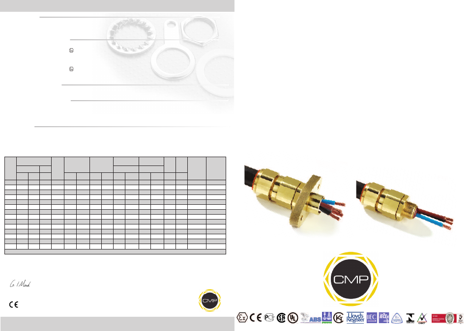
PX2KW/MF
PX2KX/MF
PX2KW/M
PX2KX/M
PX2KW/M & PX2KX/M
- PX2KW/PX2KX Gland for
Mining Applications
PX2KW/MF & PX2KX/MF
- PX2KW/M & PX2KX/M
Assembly with Flange Mount
Type MA/FT
TECHNICAL DATA
CABLE GLAND TYPE
: PX2KW/M, PX2KW/MF, PX2KX/M, PX2KX/MF
INGRESS PROTECTION
: IP66, IP67, IP68, Type 4X; Oil Resistant II
PROCESS CONTROL SYSTEM
: BS EN ISO 9001
: ISO/IEC 80079-34:2011
HAZARDOUS AREA CLASSIFICATION
GLAND
ATEX CERTIFICATION No
: SIRA 06ATEX1097X
ATEX CERTIFICATION CODE
:
IM2 Ex d I / Ex e I
IEC Ex CERTIFICATION No
: IEC Ex SIR.06.0044X
IEC Ex CERTIFICATION CODE
: Ex d I / Ex e I
MA/FT
ATEX CERTIFICATION No
: SIRA 09ATEX1034U
ATEX CERTIFICATION CODE
:
IM2 Ex d I Mb
IEC Ex CERTIFICATION No
: IEC Ex SIR.09.0024U
IEC Ex CERTIFICATION CODE
: Ex d I Mb
INSTALLATION INSTRUCTIONS
Installation should only be performed by a competent person using the correct tools. Spanners should be used for tightening. Read all
instructions before beginning installation.
SPECIAL CONDITIONS FOR SAFE USE
1. The cable gland ranges shall only be used where the temperature, at the point of entry, is in the following ranges:
-60°C to +100°C.
2. The cable glands cable are only suitable for fixed installations. Cables must be effectively clamped to prevent twisting and pulling.
3. The entry component threads may need additional sealing to maintain the ingress protection ratings as applicable to the associated
equipment to which it is attached.
ACCESSORIES
The following accessories are available from CMP Products, as optional extras, to assist with fixing, sealing and earthing :-
Locknut | Earth Tag | Serrated Washer | Entry Thread (I.P.) Sealing Washer | Shroud