CMP A2FRC User Manual
Cable, Cable gland gland type type a2frc a2frc
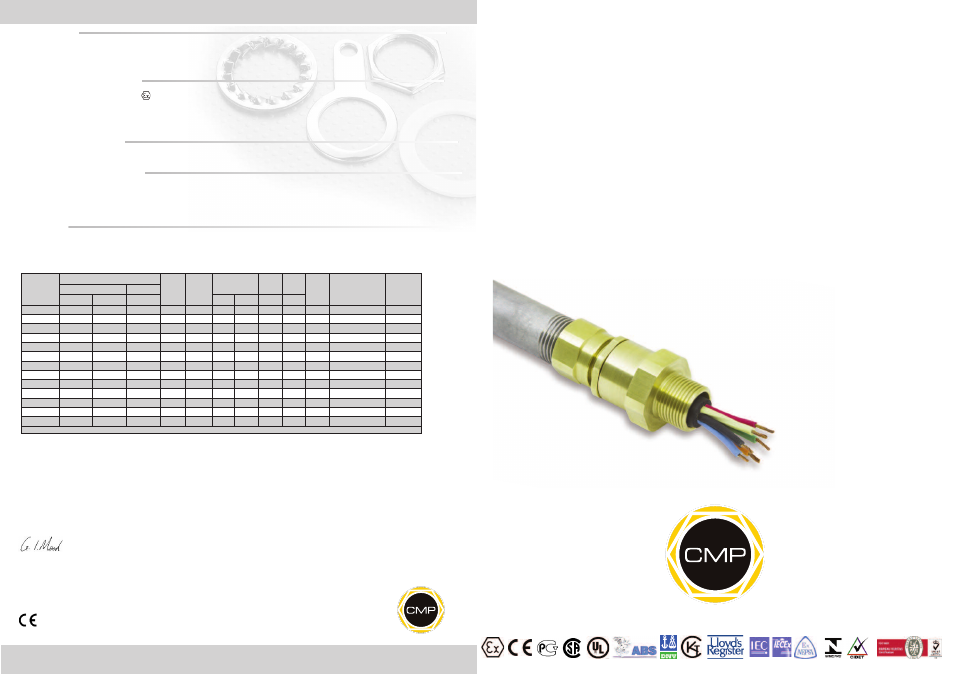
INSTALLATION INSTRUCTIONS FOR
A2FRC CABLE GLAND WITH
CONDUIT CONNECTOR
CABLE GLAND FOR USE WITH UNARMOURED AND BRAID ARMOURED CABLES HOUSED IN CONDUITS
IN HAZARDOUS AREAS.
INCORPORATING EC DECLARATION OF CONFORMITY TO DIRECTIVE 94/9/EC
CM
P
Do
cu
m
en
tN
o.
FI
44
8
Is
su
e
2
01
13
0518
Registered Office: Glasshouse Street • St. Peters • Newcastle upon Tyne • NE6 1BS
Tel: +44 191 265 7411 • Fax: +44 191 265 0581
E-Mail: [email protected] • Web: www.cmp-products.com
Company Number:
Notified Body: Sira Certification Service, Rake Lane, Chester CH4 9JN, England.
I, the undersigned, hereby declare that the equipment referred to herein conforms to the requirements of the ATEX Directive 94/9/EC and the
following standards:-
EN 60079-0:2006, EN 60079-1:2007, EN 60079-7:2007, BS 6121:1989, EN 50262:19989 (Amd 2001), EN 61241-0:2004, EN 61241-1:2004,
EN 60079-15:2005.
Dr Geof Mood - Technical Director - (Authorised Person)
DUBAI
• HOUSTON • NEWCASTLE • SINGAPORE • SHANGHAI • PUSAN • PERTH
www.cmp-products.com
Cable Gland
Size
Entry Threads
Min
Thread
Length
Standard
Female
Connection
Thread
Overall Cablle
Diameter
Across
Flats
Across
Corners Nominal
Protrusion
Length
Ordering Reference
(Brass Metric Male x NPT
Female)
Cable Gland
Weight (Kgs)
Standard
Option
Metric
NPT
NPT
Min
Max
Max
Max
20S/16
M20
1/2”
3/4”
15.0
1/2”
3.2
8.7
24.0
25.9
37.0
20S16A2FRC1RA031
0.054
20S
M20
1/2”
3/4”
15.0
1/2”
6.1
11.7
24.0
25.9
37.0
20SA2FRC1RA031
0.054
20
M20
1/2”
3/4”
15.0
1/2”
6.5
14.0
27.0
29.2
37.0
20A2FRC1RA031
0.059
25
M25
3/4”
1”
15.0
3/4”
11.1
20.0
36.0
38.9
39.0
25A2FRC1RA032
0.112
32
M32
1”
1-1/4”
15.0
1”
17.0
26.3
36.0
38.9
41.0
32A2FRC1RA033
0.128
40
M40
1-1/4”
1-1/2”
15.0
1-1/4”
23.5
32.2
46.0
49.7
42.0
40A2FRC1RA034
0.168
50S
M50
1-1/2”
2”
15.0
1-1/2”
31.0
38.2
50.0
54.0
48.0
50SA2FRC1RA035
0.224
50
M50
2”
2-1/2”
15.0
2”
35.6
44.1
65.0
70.2
51.0
50A2FRC1RA036
0.231
63S
M63
2”
2-1/2”
15.0
2”
41.5
50.0
65.0
70.2
50.0
63SA2FRC1RA036
0.360
63
M63
2-1/2”
3”
15.0
2-1/2”
47.2
56.0
80.0
86.4
50.0
63A2FRC1RA037
0.344
75S
M75
2-1/2”
3”
15.0
2-1/2”
54.0
62.0
80.0
86.4
60.0
75SA2FRC1RA037
0.466
75
M75
3”
3-1/2”
15.0
3”
61.1
68.0
100.0
108.0
60.0
75A2FRC1RA038
0.395
90
M90
3”
3-1/2”
15.0
3”
61.6
80.0
100.0
108.0
79.0
90A2FRC1RA038
1.346
All dimensions in millimeters
Ca
bl
e
Gl
an
d
Se
le
ct
io
n
Ta
bl
e
Logo’s shown for illustration purposes only. Please check certification for details
CABLE
CABLE
GLAND
GLAND
TYPE
TYPE
A2FRC
A2FRC
NOTE: Other thread forms, materials and finishes are available. IEC Ex, ATEX & CSA hazardous area certification marking included as standard. Please consult CMP for any other
requirements.
TECHNICAL DATA
CABLE GLAND TYPE
: A2FRC
INGRESS PROTECTION
: IP66, NEMA 4X
PROCESS CONTROL SYSTEM
: BS EN ISO 9001
: ISO/IEC 80079-34:2011
HAZARDOUS AREA CLASSIFICATION
ATEX CERTIFICATION No
: SIRA06ATEX1097X, SIRA07ATEX4326X
ATEX CERTIFICATION CODE
:
II 2 GD Ex d IIC, Ex e II, Ex nR II, Ex tD A21 IP66
IEC Ex CERTIFICATION No
: IEC Ex SIR.06.0040X
IEC Ex CERTIFICATION CODE
: Ex d IIC / Ex e II / Ex nR II, Ex tD A21 IP66
CSA CERTIFICATION No
: 1211841
CSA CERTIFICATION CODE
: Ex d IIC & Ex e II, CSA Enclosure Type 4X
INSTALLATION INSTRUCTIONS
Installation should only be performed by a competent person using the correct tools. Spanners should be used for tightening. Read all instructions
before beginning installation.
SPECIAL CONDITIONS FOR SAFE USE
1.
The A2FRC shall only be used where the temperature, at the point of entry, is between -60°C and +130°C.
2.
The entry component threads may need additional sealing to maintain the ingress protection rating as applicable to the associated
equipment to which it will be attached.
3.
If used to connect to flexible conduit, the conduit must be clamped to prevent pulling or twisting of the cable.
ACCESSORIES
The following accessories are available from CMP Products, as optional extras, to assist with fixing, sealing and earthing :-
Locknut | Earth Tag | Serrated Washer | Entry Thread (I.P.) Sealing Washer | Shroud*