CMP E2FWC User Manual
Cable gland types, Cable gland types e1fwc & e2fwc e1fwc & e2fwc
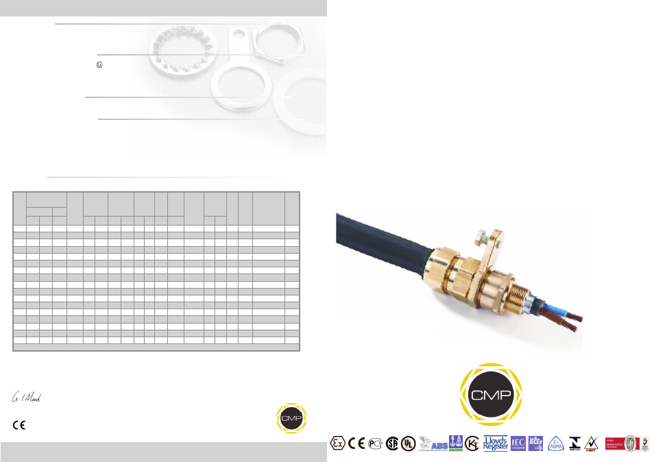
INSTALLATION INSTRUCTIONS FOR
CMP CABLE GLAND TYPE “E” WITH
CAST INTEGRAL EARTH LUG
FOR TERMINATION OF CABLES WITH SINGLE WIRE ARMOUR (SWA) (WITH LEAD INNER SHEATH ON
“E2” VARIANT). FOR USE IN HAZARDOUS LOCATIONS, INCORPORATING A CAST INTEGRAL EARTH LUG.
INCORPORATING EC DECLARATION OF CONFORMITY TO DIRECTIVE 94/9/EC
CM
P
Do
cu
m
en
tN
o.
FI
42
1
Is
su
e
3
01
/1
3
0518
Glasshouse Street • St. Peters • Newcastle upon Tyne • NE6 1BS
Tel: +44 191 265 7411 • Fax: +44 191 265 0581
E-Mail: [email protected] • Web: www.cmp-products.com
Notified Body: Sira Certification Service, Rake Lane, Chester CH4 9JN, England.
I, the undersigned, hereby declare that the equipment referred to herein conforms to the requirements of the ATEX Directive 94/E/EC and the following
standards:-
EN60079-0:2006, EN60079-1:2007, EN60079-7:2007, EN60079-15:2005, BS 6121:1989, EN50262:1998 (Amd 2001), EN61241-0:2004, EN61241-1:2004
Dr Geof Mood - Technical Director - (Authorised Person)
DUBAI
• HOUSTON • NEWCASTLE • SINGAPORE • SHANGHAI • PUSAN • PERTH
www.cmp-products.com
Ca
bl
e
Gl
an
d
Se
le
ct
io
n
Ta
bl
e
Logo’s shown for illustration purposes only. Please check certification for details
CABLE GLAND TYPES
CABLE GLAND TYPES
E1FWC & E2FWC
E1FWC & E2FWC
# Order codes shown are for E1FUC glands
For e.g. E1FWC glands substitue E1FWC for E1FUC - e.g. 20E1FWC1RA
Please note that the overall maximum cable bedding diameter for “E2” variants should be reduced by 1mm to allow for the inner lead sheath.
E1FWC - SWA Armour
E2FWC - SWA Armour for lead
sheathed cable
Cable
Gland
Size
Available Entry
Threads
Thread
Length
metric
Cable
Bedding
Diameter
Overall Cable
Diameter
Armour
Range
Across
Flats
Across
Corners
Nominal
Protrusion
Length
Nominal
Radius
Dimension
CIEL
Earth
Bolt
Size
Earth
Fault
Current
Rating
(kA)
Ordering
Reference
(Brass Metric)
#
Cable
Gland
Weight
(Kgs)
Standard
Option
Metric NPT
NPT 2
Min
Max
Min
Max
Min Max
Max
Max
bolt
lug
20S/16 M20
1/2”
3/4”
15.0
3.1
8.6
6.1
13.2
0.9
1.0
24.0
25.9
58.5
28.6 38.6
M8
26.0
20S16E1FUC1RA
0.162
20S
M20
1/2”
3/4”
15.0
6.1
11.6
9.5
15.9
0.9 1.25 24.0
25.9
58.5
28.6 38.6
M8
26.0
20SE1FUC1RA
0.162
20
M20
1/2”
3/4”
15.0
6.5
13.9
12.5
20.9
0.9 1.25 30.5
32.9
60.5
31.8 41.8
M8
26.0
20E1FUC1RA
0.211
25S
M25
3/4”
1”
15.0
11.1
19.9
14.0
22.0 1.25 1.6
37.5
40.5
67.5
31.8 50.8
M8
26.0
25SE1FUC1RA
0.330
25
M25
3/4”
1”
15.0
11.1
19.9
18.2
26.2 1.25 1.6
37.5
40.5
67.5
38.1 50.8
M8
26.0
25E1FUC1RA
0.330
32
M32
1”
1-1/4”
15.0
17.0
26.2
23.7
33.9
1.6
2.0
46.0
49.7
69.5
41.3 54.0 M10
26.0
32E1FUC1RA
0.452
40
M40 1-1/4” 1-1/2”
15.0
22.0
32.1
27.9
40.4
1.6
2.0
55.0
59.4
78.0
50.8 69.0 M12
26.0
40E1FUC1RA
0.657
50S
M50 1-1/2”
2”
15.0
29.5
38.1
35.2
46.7
2.0
2.5
60.0
64.8
75.5
57.2 75.0 M12
43.0
50SE1FUC1RA
0.734
50
M50
2”
2-1/2”
15.0
35.6
44.0
40.4
53.1
2.0
2.5
70.0
75.6
80.5
60.3 80.0 M12
43.0
50E1FUC1RA
0.748
63S
M63
2”
2-1/2”
15.0
40.1
49.9
45.6
59.4
2.0
2.5
75.0
81.0
91.5
70.0 90.0 M12
43.0
63SE1FUC1RA
1.337
63
M63 2-1/2”
3”
15.0
47.2
55.9
54.6
65.9
2.0
2.5
80.0
86.4
92.0
69.9 90.0 M12
43.0
63E1FUC1RA
1.436
75S
M75 2-1/2”
3”
15.0
52.8
61.9
59.0
72.1
2.0
2.5
89.0
96.1
99.0
76.2 97.0 M12
43.0
75SE1FUC1RA
2.073
75
M75
3”
3-1/2”
15.0
59.1
67.9
66.7
78.5
2.0
3.0
99.0
106.9
102.0
88.9 108.0 M12
43.0
75E1FUC1RA
2.622
90
M90 3-1/2”
4”
24.0
66.6
79.9
76.2
90.4
3.0
3.5 114.0
123.1
120.0
95.3 112.0 M12
43.0
90E1FUC1RA
4.174
100
M100
-
-
24.0
76.0
90.9
86.1
101.5 3.15 4.0 123.0
132.8
148.0
95.3 112.0 M12
43.0
100E1FUC1RA
4.523
115
M115
-
-
24.0
86.0
97.9
101.3 110.3 3.15 4.0 133.4
133.4
169.0
95.3 112.0 M12
43.0
115E1FUC1RA
6.860
130
M130
-
-
24.0
97.0 114.9 114.0 123.3 3.15 4.0 146.1
146.1
183.0
95.3 112.0 M12
43.0
130E1FUC1RA
8.121
All dimensions in millimetres
TECHNICAL DATA
CABLE GLAND TYPE
: E** Family of CIEL Cable Glands
INGRESS PROTECTION
: IP66, IP67, IP68
PROCESS CONTROL SYSTEM
: BS EN ISO 9001
: ISO/IEC 80079-34:2011
HAZARDOUS AREA CLASSIFICATION
ATEX CERTIFICATION No
: SIRA 06ATEX1097X & SIRA 07ATEX4326X
ATEX CERTIFICATION CODE
:
II 2 GD Ex d IIC / Ex e IIC / Ex nR II / Ex tD A21 IP66
IEC Ex CERTIFICATION No
: IEC Ex SIR.06.0043X
IEC Ex CERTIFICATION CODE
: Ex d IIC / Ex e IIC / Ex nR II / Ex tD A21 IP66
CSA CERTIFICATION No
: 02.1310517
CSA CERTIFICATION CODE
: Ex d IIC / Ex e II
INSTALLATION INSTRUCTIONS
Installation should only be performed by a competent person using the correct tools. Spanners should be used for tightening. Read all instructions
before beginning installation.
SPECIAL CONDITIONS FOR SAFE USE
For ATEX & IEC Ex certification:
1. The E type glands shall only be used where temperatures at the point of entry is between -60°C and +130°C.
2. E type glands used for terminating braided cables are only suitable for fixed installations. Cables must be clamped to prevent pulling or twisting.
3. An entry thread seal may be need to maintain the IP rating of the enclosure to which the E type gland is attached.
FOR CSA Certification:
1. These glands are not suitable for use with flameproof enclosures installed in Group IIC atmospheres which have a volume greater than 2000 cc (2
Litre).
2. These glands are for use with Certified Marine Shipboard metal braided cables constructed in according to CSA Std. 245 and
IEEE45/IEC600092-353 Standards, or Certified equivalent), for use on Shipboards and Offshore Rigs/Platfords only
ACCESSORIES
The following accessories are available from CMP Products, as optional extras, to assist with fixing, sealing and earthing :-
Locknut | Serrated Washer | Entry Thread (I.P.) Sealing Washer