CMP TMC2X User Manual
Cable, Cable connector connector type type tmc2x tmc2x
INSTALLATION INSTRUCTIONS FOR
CMP CABLE CONNECTOR TYPE
TMC2X
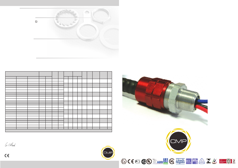
CMP TYPE TMC2X CABLE CONNECTOR FOR USE WITH INTERLOCKED & CORRUGATED CONTINUOUSLY
WELDED METAL CLAD (TYPE MC OR MC-HL) OR TECK ARMORED AND ARMORED & JACKETED CABLES
IN ORDINARY, WET & HAZARDOUS LOCATIONS.
INCORPORATING EC DECLARATION OF CONFORMITY TO DIRECTIVE 94/9/EC
CM
P
Do
cu
m
en
tN
o.
FI
46
6
Is
su
e
2
02
/1
3
0518
Registered Office: Glasshouse Street • St. Peters • Newcastle upon Tyne • NE6 1BS
Tel: +44 191 265 7411 • Fax: +44 191 265 0581
E-Mail: [email protected] • Web: www.cmp-products.com
Notified Body: Sira Certification Service, Rake Lane, Chester CH4 9JN, England.
I, the undersigned, hereby declare that the equipment referred to herein conforms to the requirements of the ATEX Directive 94/9/EC and the following
standards:-
EN60079-0:2009, EN60079-1:2007, EN60079-7:2007, BS 6121:1989, EN50262:1998 (Amd 2001), EN61241-0:2006, EN61241-1:2004
Dr Geof Mood - Technical Director - (Authorised Person)
DUBAI
• HOUSTON • NEWCASTLE • SINGAPORE • SHANGHAI • PUSAN • PERTH
www.cmp-products.com
Ordering Reference
(Std Thread)
Entry Thread
NPT
Diameter
Over
Cores
Min
Thread
Length
Cable Armor
Diameter
Cable Jacket
Diameter
Across
Flats
Range
Across
Corners
Assembled
Length
Approx
Weight
Aluminium
(ozs)
Gland
Size
Aluminium
NP Brass
S. Steel
Standard Option
Min
Max
Min
Max
TMC2X-050A075
TMC2X-050NB075
TMC2X-050SS075
1/2”
-
0.51
0.78
0.42
0.63
0.50
0.75
1.20
1.30
1.65
2.29
20S
TMC2X-075A075
TMC2X-075NB075
TMC2X-075SS075
-
3/4”
0.51
0.80
TMC2X-075A099
TMC2X-075NB099
TMC2X-075SS099
3/4”
-
0.71
0.80
0.60
0.89
0.69
0.99
1.48
1.60
1.97
3.00
20
TMC2X-050A099
TMC2X-050NB099
TMC2X-050SS099
-
1/2”
0.51
0.78
TMC2X-100A118
TMC2X-100NB118
TMC2X-100SS118
1”
-
0.94
0.98
0.79
1.10
0.87
1.18
1.81
1.95
2.13
5.11
25
TMC2X-075A118
TMC2X-075NB118
TMC2X-075SS118
-
3/4”
0.71
0.80
TMC2X-125A137
TMC2X-125NB137
TMC2X-125SS137
1-1/4”
-
1.20
1.00
0.94
1.28
1.02
1.37
2.05
2.21
2.34
6.70
32
TMC2X-100A137
TMC2X-100NB137
TMC2X-100SS137
-
1”
0.94
0.98
TMC2X-150A162
TMC2X-150NB162
TMC2X-150SS162
1-1/2”
-
1.46
1.03
1.22
1.50
1.30
1.62
2.36
2.55
2.44
8.82
40S
TMC2X-125A162
TMC2X-125NB162
TMC2X-125SS162
-
1-1/4”
1.20
1.00
TMC2X-150A190
TMC2X-150NB190
TMC2X-150SS190
1-1/2”
-
1.46
1.03
1.49
1.72
1.57
1.90
2.56
2.76
2.44
9.45
40
TMC2X-125A190
TMC2X-125NB190
TMC2X-125SS190
1-1/4”
1.20
1.00
TMC2X-200A200
TMC2X-200NB200
TMC2X-200SS200
2”
-
1.63
1.06
1.57
1.88
1.65
2.00
2.75
2.97
2.60
11.06
50S
TMC2X-150A200
TMC2X-150NB200
TMC2X-150SS200
-
1-1/2”
1.46
1.03
TMC2X-250A233
TMC2X-250NB233
TMC2X-250SS233
2-1/2”
-
2.13
1.57
1.79
2.21
1.91
2.33
2.95
3.19
2.64
12.77
63S
TMC2X-200A233
TMC2X-200NB233
TMC2X-200SS233
-
2”
1.90
1.06
TMC2X-300A272
TMC2X-300NB272
TMC2X-300SS272
3”
-
2.55
1.63
2.14
2.61
2.27
2.72
3.54
3.82
2.76
24.69
75
TMC2X-250A272
TMC2X-250NB272
TMC2X-250SS272
-
2-1/2”
2.37
1.57
TMC2X-350A325
TMC2X-350NB325
TMC2X-350SS325
3-1/2”
-
2.98
1.68
2.49
2.97
2.62
3.25
4.33
4.68
3.46
42.68
90
TMC2X-300A325
TMC2X-300NB325
TMC2X-300SS325
-
3”
2.98
1.63
TMC2X-400A376
TMC2X-400NB376
TMC2X-400SS376
4”
-
3.49
1.73
2.95
3.54
3.16
3.76
4.84
5.23
3.68
53.44
100
TMC2X-350A376
TMC2X-350NB376
TMC2X-350SS376
-
3-1/2”
3.49
1.68
TMC2X-400A425
TMC2X-400NB425
TMC2X-400SS425
4”
-
3.49
1.73
3.52
3.94
3.70
4.25
5.23
5.65
3.89
59.19
115
All dimensions in inches
Ca
bl
e
Co
nn
ec
to
rS
el
ec
tio
n
Ta
bl
e
Logo’s shown for illustration purposes only. Please check certification for details
CABLE
CABLE
CONNECTOR
CONNECTOR
TYPE
TYPE
TMC2X
TMC2X
TECHNICAL DATA
CABLE GLAND TYPE
: TMC2X
INGRESS PROTECTION
: IP66, NEMA 4X
PROCESS CONTROL SYSTEM
: BS EN ISO 9001
: ISO/IEC 80079-34:2011
HAZARDOUS AREA CLASSIFICATION
ATEX CERTIFICATION No
: SIRA 09ATEX1165X
ATEX CERTIFICATION CODE
:
II 2 GD Exd IIC Gb / Ex e IIC Gb / Ex ta IIIC Da
IEC Ex CERTIFICATION No
: IEC Ex SIR.09.0069X
IEC Ex CERTIFICATION CODE
: Ex d IIC Gb / Ex e IIC Gb / Ex ta IIIC Da
CSA-us CERTIFICATION No
: CSA.09.2194053X
CSA-us CERTIFICATION CODE
: Class I Div 1, 2 Gp A, B, C, D; Class II, Div 1, 2 Gp E, F, G; Class 1 Zone 1, 2, AEx d IIC, AEx e II;
Ex d IIC, Ex e II; SL
INSTALLATION INSTRUCTIONS
Installation should only be performed by a competent person using the correct tools. Read all instructions before beginning installation.
INSTALLATION GUIDANCE NOTES
1. In accordance with NEC requirements, connectors with NPT and Metric entry threads are suitable for both Divisions and Zones.
2. In accordance with CEC requirements, connectors with NPT threads are suitable for both Divisions and Zones. Connectors with Metric threads are
only suitable for Zones unless fitted with an approved Metric to NPT thread conversion adaptor.
3. For IEC and/or ATEX installations:
- All tapes/shields/foils must be removed and any twisted pairs/triples unwound to form individual conductors.
- Drain Wires: Pass sleeving/heat shrink tube over the drain, making sure it is positioned within the resin Tube/Resin Dam area.
If required, shrink the tube by applying heat, then treat the drain wire as a conductor.
4. For NEC Class 1 Div 1 and Zone 1 see article 501.15 of the NEC.
SPECIAL CONDITIONS FOR SAFE USE
• The glands shall only be fitted to enclosures where temperatures, at the point of mounting, is below 85°C.
• The cable shall be effectively clamped as close as possible to the gland.
• When used for Ex e or Ex ta applications, the user shall provide a suitable interface seal between the gland and associated enclosure to maintain
the level of ingress protection of the enclosure they are fitted to.