CMP PX2KX/MF User Manual
Page 2
DUBAI
• HOUSTON • NEWCASTLE • SINGAPORE • SHANGHAI • PUSAN • PERTH
DUBAI
• HOUSTON • NEWCASTLE • SINGAPORE • SHANGHAI • PUSAN • PERTH
www.cmp-products.com
www.cmp-products.com
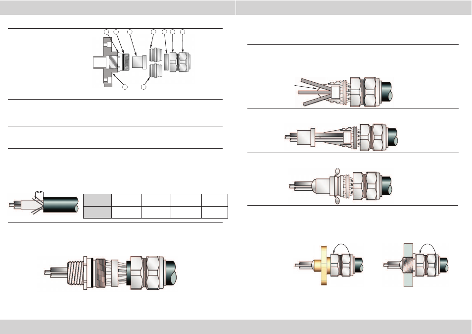
CABLE GLAND COMPONENTS
PLEASE READ ALL INSTRUCTIONS CAREFULLY BEFORE BEGINNING THE INSTALLATION
1. The illustration shows two armour cones, the grooved armour cone (5a) is suitable for Strip Armour,
Tape Armour and Braided Cables, and the stepped cone (5b) is suitable for Wire Armour (SWA) cables.
The PX2KX/M & PX2KX/MF gland only has one cone (5a) and the PX2KW/M & PX2KW/MF only has one
cone (5b).
2. Separate the gland components by removing the body and outer seal nut assembly. Pass the body
and outer seal nut assembly (6),(8), and the AnyWay clamping ring (7) over the cable, outer seal nut
first.
3. Prepare the cable by stripping back the outer sheath and braid / armour to suit the equipment.
Expose the braid or armour further so that it can be formed around the armour cone by cutting back
the outer sheath by a length “L”. This length varies slightly depending upon cable diameter, but typical
values are shown below. The inner sheath should be long enough to just pass through the armour
cone when installed.
4. For direct make-off, fit the entry item to the equipment. Insert the armour cone (5a or 5b) into the
entry item (2) and pass the cable through them until the braid or armour contacts the cone and make
sure that it is evenly spaced around it. Tighten the body (6) to lock the braid or armour and then
slacken and remove the body again, withdrawing the cable with it.
5. Remove any bedding or fillers from around the cable cores. If the cable cores have screens,
these should be unravelled and then twisted together to form a single core.
Wearing the protective gloves supplied, mix all of the two-part epoxy compound until it is pliable
and an even colour is achieved (minimum mixing temperature 10°C).
6. Separate the cores and apply the compound to the crutch of the cable for a distance of about
6mm and pack into place.
If a drain wire is present then it should be sleeved using some heat shrink tubing which is pushed
into the compound before shrinking with the application of some heat.
If screens have been twisted together at stage 5, also be sleeved using heat shrink sleeving.
7. Bring the cores together again and pack more compound around them to a length and diameter
sufficient to fill the compound tube, ending in a taper.
8. Pass the compound tube (3) over the conductors until the stepped end is fully located with the
armour cone (5). Pack more compound into place until the compound tube is fully filled
9. Re-install the cable assembly into the entry item making sure that the compound is not disturbed
and fully tighten the body (6) onto the entry item (2). Tighten the outer seal nut assembly (8)
until it comes to an effective stop. This will occur when :-
A) The outer seal nut (8) has clearly engaged the cable and cannot be further tightened
without the use of excessive force by the installer.
B) The outer seal nut (8) is metal to metal with the body of the gland (6).
The gland and conductors must be left undisturbed to allow the compound to cure. This may take
up to 24 hours depending upon temperature.
5b
5a
3
4
1. Compound (EP2122)
2. Entry Component
3. Compound Tube
4. “O” Ring
5a. Grooved Armour Cone (X)
5b. Stepped Armour Cone (W)
6. Body
7. AnyWay Clamping Ring
8. Outer Seal Nut Assembly
9. Optional Flanged Adaptor
CABLE
GLAND SIZE 20S/16, 20S, 20 25S, 25, 32, 40 50S, 50, 63S, 63 75S, 75, 90
CABLE STRIP
LENGTH “L”
12 mm
(0.472 inches)
15 mm
(0.591 inches)
18 mm
(0.709 inches)
20 mm
(0.787inches)
6
7
8
L
Crutch of the
cable
INSTALLATION INSTRUCTIONS FOR CMP CABLE GLAND TYPES:
PX2KW/M, PX2KW/MF, & PX2KX/M, PX2KX/MF
2
9
Optional flange
adaptor