CMP C2KX User Manual
Page 2
DUBAI
• HOUSTON • NEWCASTLE • SINGAPORE • SHANGHAI • PUSAN • PERTH
DUBAI
• HOUSTON • NEWCASTLE • SINGAPORE • SHANGHAI • PUSAN • PERTH
www.cmp-products.com
www.cmp-products.com
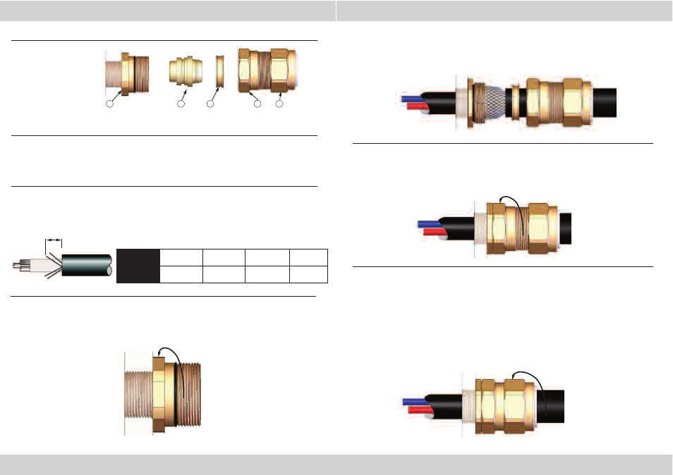
INSTALLATION INSTRUCTIONS FOR CMP CABLE GLAND TYPE C2KX
PLEASE READ ALL INSTRUCTIONS CAREFULLY BEFORE BEGINNING THE INSTALLATION
1. Slacken the Outer Seal Assembly (5), but do not remove it from the Body (4). Seperate the gland
components by removing the Body (4) and the Outer Seal Assembly (5) as one unit. (Note that the
Detachable Armour Cone (2) and AnyWay Clamping Ring (3) are loose items). Pass the Body (4), Outer
Seal Assembly (5) and AnyWay Clamping Ring (3) over the cable, Outer Seal Assembly (5) first.
2. Prepare the cable by stripping back the outer sheath and braid to suit the equipment. Expose the
braid or armour further so that it can be formed around the armour cone by cutting back the outer
sheath by a length “L”. This length varies slightly depending upon the cable diameter, but typical values
are shown below.
3. Secure the Entry Component (1) to the equipment by tightening with a spanner.
4. Locate the Detachable Armour Cone (2) in the Entry Component (1). Pass the cable through the
Cone (2) and Entry Component (1), evenly spacing the braid around the Cone (2).
5. While continuing to gently push the cable forward to keep the braid in contact with the Cone (2),
tighten the Body (4) first by hand and then with a spanner until the Body (4) is fully tightened onto
the Entry Component (1) and no threads are visible.
6. Tighten the Outer Seal Nut Assembly (5) until it comes to an effective stop.
This will occur when:-
A)
The Outer Seal Nut Assembly (5) has clearly engaged the cable and cannot be further
tightened without the use of excessive force by the installer.
B)
The Outer Seal Nut Assembly (5) has been fully tightened. (This will only happen if
the cable is at the bottom end of the range for the gland).
For Guidance:- The Outer Seal Assembly (5) is correctly fitted when it has been tightened until the
seal touches the cable sheath and then tightened a further one turn using a spanner.
3
2
1
1. Entry Component
2. Detachable Armour Cone
3. AnyWay Clamping Ring
4. Body
5. Outer Seal Assembly
4
5
CABLE GLAND COMPONENTS
CABLE GLAND
SIZE
20S/16, 20S, 20 25S, 25, 32, 40 50S, 50, 63S, 63 75S, 75, 90
CABLE STRIP
LENGTH “L”
12 mm
(0.472 inches)
15 mm
(0.591 inches)
18 mm
(0.709 inches)
20 mm
(0.787 inches)
L