CMP TMC2X User Manual
Page 2
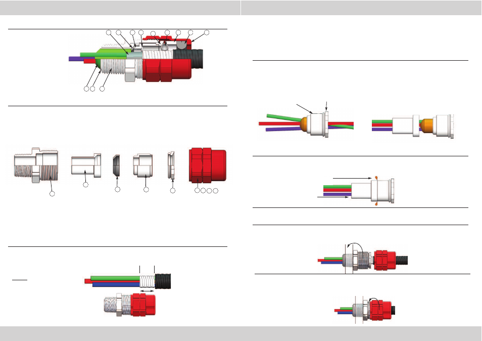
INSTALLATION INSTRUCTIONS FOR TMC2X CABLE CONNECTOR
DUBAI
• HOUSTON • NEWCASTLE • SINGAPORE • SHANGHAI • PUSAN • PERTH
www.cmp-products.com
www.cmp-products.com
PLEASE READ ALL INSTRUCTIONS CAREFULLY BEFORE BEGINNING THE INSTALLATION
1. Disasemble the connector by unscrewing the entry item (3) from the rest of the connector
and then unscrewing the spacer nut (8) from the entry component.
1
2
3
12
10
9
8
11
7
6
5
4
1. Compound
2. Compound Tube
3. Entry Item
4. Sealant Tape or Inner Jacket
5. Resin Dam (Optional)
6. Tube Spacer
7. End Stop
8. Spacer Nut
9. Grounding Spring
10. Angled Spacer
11. Jacket Seal
12. Outer Nut
NOTE: When the outer
jacket is at its
maximum, distance “L”
may have to be
increased by up to 10%.
3. Slide the outer nut assembly (9,10,11,12) down the cable. Pass the space nut (8) and tube
spacer (6) with nylon end stop (7) over the conductors until the end stop engages the end of the
cable armour. (If the nylon end stop will not pass over the conductors, then it should be discarded
as it is not needed.)
At this stage it should be possible to acces the tube spacer nut (8). If this is not possible, trim the
outer jacket up to the “L” +10% until access is possible.
8. Once the compound has cured, loosen the Tube Spacer Nut from the Entry Component. Screw
the Entry Component into the enclosure. Retighten the Tube Spacer Nut when the entry component
is fully tightened into the enclosure.
9. Finally, holding the cable central in the gland, tighten the Outer Nut to compress the Grounding
Spring to secure the armor and the seal to engage the cable jacket. Do not over tighten the
Outer Nut. The Entry Component and Outer Nut do not have to close face to face.
2. Strip back the jacket and armour to suit the equipment. Using the armor measure guide, expose
the armor further by stripping the cable jacket to distance “L”.
L
L = Distance from
groove to rear of nut.
DUBAI
• HOUSTON • NEWCASTLE • SINGAPORE • SHANGHAI • PUSAN • PERTH
CABLE CONNECTOR COMPONENTS
3
2
5
6
8
Remove and discard the resin dam (5). (This part is only needed when the connector is used
with the RapidEx resin system.)
4. Wearing the protective gloves supplied, thoroughly mix the two-part compound until the colour is
uniform. (The compound should not be mixed or applied at temperatures below 50°F/10°C.)
Seperate the cores of the conductor and pack the compound between and around the conductors
as shown below:
9
10 11 12
5. Bring the cores together again and pack
more compound around them to a length
and diameter sufficient to fill the
compound tube, ending in a taper.
6. Pass the compound tube (2) over the conductors until the stepped end is fully located with the
tube spacer (6). Pack more compound into place until the compound tube is fully filled.
7. Reinstall the cable assembly into the Entry Item (3) and tighten the Spacer Nut (8), finger-tight.
Leave for the compound to cure.
Remove surplus compound
Note: For instrumentation cable utilising shielded cable or industrial / overall drain wires see
installation guidance notes on the back page.
Ensure compound does
not overlap the tube
Tube Spacer
Spacer Nut