CMP E2FWC User Manual
Page 2
INSTALLATION INSTRUCTIONS FOR CMP CABLE GLAND TYPE “E”
DUBAI
• HOUSTON • NEWCASTLE • SINGAPORE • SHANGHAI • PUSAN • PERTH
www.cmp-products.com
www.cmp-products.com
PLEASE READ ALL INSTRUCTIONS CAREFULLY BEFORE BEGINNING THE INSTALLATION
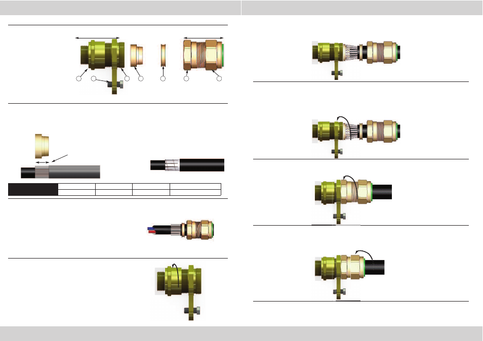
1.
Prepare the cable by stripping back the cable outer sheath and armour to suit the equipment
geometry. Expose the armour by stripping back the outer sheath further using the table below
as a guide. If applicable remove any tapes or wrappings to expose cable inner sheath.
2.
Separate the gland into two sub-assemblies “A & B”.
Ensuring that the Outer Seal Nut (6) is relaxed, pass
sub-assembly “B” over the cable outer sheath and
armour followed by the “AnyWay” clamping ring (4).
Note: On maximum size cables the clamping ring may
only pass over the armour.
4.
Locate the Armour Cone (3) into its recess in the Main Item (2). (N.B. For E1FU and E2FU
variants, make sure the correct side of the cone is outermost - grooved for braid/tape
armour and stepped for SWA). Pass the cable through sub-assembly “A” until the armour
engaged with the cone. Spread the armour evenly around the cone.
5.
While continuing to push the cable forward to maintain contact between the armour and the
cone, tighten the Main Item (2) by hand until extra resistance is felt. (This is when the
inner seal makes contact with the cable inner sheath). Tighten a further full turn using a
spanner.
NOTE: The earthing device on E2* type glands will automatically engage the lead sheath.
6.
Hold the Main Item (2) with a spanner and tighten sub-assembly “B” onto sub-assembly “A”
using a spanner until all available threads are used.
7.
Tighten the Outer Seal Nut (6) until it comes to an effective stop. This will occur when:-
A)
The Outer Seal Nut (6) has clearly engaged the cable and cannot be further tightened
without the use of excessive force by the installer.
B)
The Outer Seal Nut (6) is metal to metal with the body of the gland (5).
8.
Connect the earth cable to the earth bolt.
3
2
1. Entry Component
2. Main Item with CIEL
3. Detachable Armour Cone
4. AnyWay Clamping Ring
5. Body
6. Outer Seal Nut
7. Earth Bolt
4
6
Sub Assembly A
Sub Assembly B
5
CABLE GLAND COMPONENTS - It is not necessary to dismantled the cable gland any further than illustrated below
7
1
3.
Ensure that the inner seal is relaxed by slackening
the Main Item (2). Secure sub-assembly “A” into the
equipment either by screwing the Entry Item (1)
into a threaded hole or by securing it in a clearance
hole using a locknut as applicable.
CABLE GLAND SIZE
20S/16, 20S, 20
25S, 25, 32, 40
50S, 50, 63S, 63 75S, 75, 90, 100, 115, 130
CABLE STRIP LENGTH “L”
12mm
15mm
18mm
20mm
Tape armour should be further
prepared by cutting the tape
into strips as shown below:
Cable Strip
Length “L”
DUBAI
• HOUSTON • NEWCASTLE • SINGAPORE • SHANGHAI • PUSAN • PERTH