CMP CX User Manual
Page 2
INSTALLATION INSTRUCTIONS FOR CMP CABLE GLAND TYPES CW & CX
DUBAI
• HOUSTON • NEWCASTLE • SINGAPORE • SHANGHAI • PUSAN • PERTH
DUBAI
• HOUSTON • NEWCASTLE • SINGAPORE • SHANGHAI • PUSAN • PERTH
www.cmp-products.com
www.cmp-products.com
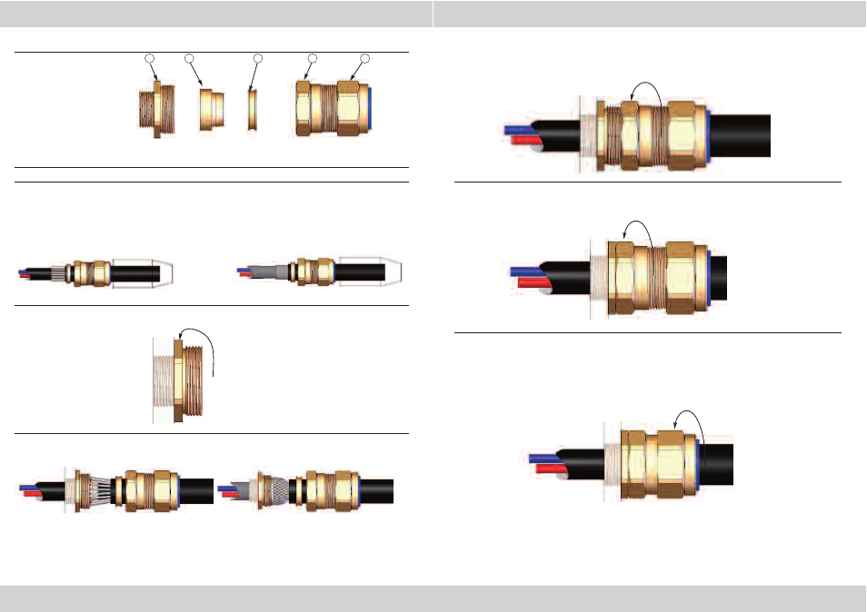
CABLE GLAND COMPONENTS
PLEASE READ ALL INSTRUCTIONS CAREFULLY BEFORE BEGINNING THE INSTALLATION
1. Separate components (1), (2) and (3) from Sub-Assembly B. If required, fit a shroud over the cable
outer sheath. Prepare the cable by removing the cable outer sheath and the braid/armour to suit the
geometry of the equipment.
Remove a further 18mm (max) of outer sheath to expose the armour. If applicable remove any tapes
or wrappings to expose the inner sheath.
NOTE: On maximum size cables the clamping ring may only pass over the armour.
2. Secure the Entry Component (1) into the equipment as indicated.
3. Locate the Detachable Armour Cone (2) into the Entry Component. Pass the cable through the entry
item and evenly space the braid/armour around the cone.
4. While continuing to push the cable forward to maintain contact between the braid armour and
the Cone (2), tighten the Body (4) by hand until the AnyWay Clamping Ring (3) is felt to have
engaged the braid/armour.
Hold the Entry Component (1) with a spanner and tighten the Body (4) using a spanner until all
available threads are used.
5. Ensure the Entry Item (1) and Body (4) are fully tightened together
6. Tighten the Outer Seal Nut (5) until it comes to an effective stop. This will occur when:-
A) The Outer Seal Nut (5) has clearly engaged the cable and cannot be further tightened
without the use of excessive force by the installer.
B) The Outer Seal Nut (5) is metal to metal with the body of the gland (4).
4
3
2
1
1.
Entry Component
2.
Detachable Armour Cone
3.
AnyWay Clamping Ring
4.
Body
5.
Outer Seal Nut
5
(A SWA cone is shown in the illustration, but the cable gland will be supplied with the correct cone - stepped
type for CW glands and grooved type for CX glands.
SWA
BRAID
SWA
BRAID