BMR Suspension BK005 User Manual
Page 5
Rear Upper Control Arm Bushing
BK005 (Continued)
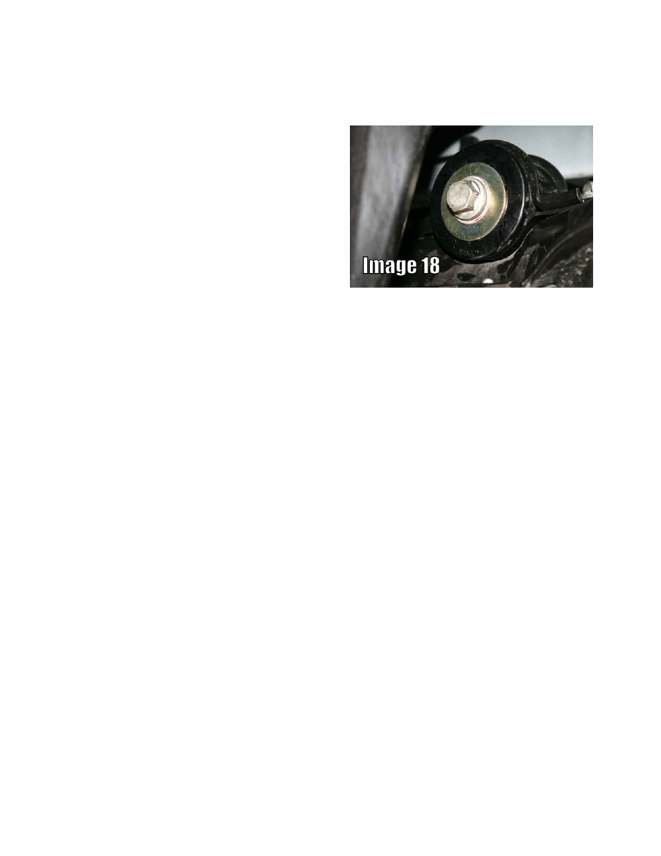
20. Position the bushing shell to match
the original orientation then push
the BMR bushing into the shell
with the flange of the bushing
towards the outside of the A-arm.
Insert the provided sleeve then
attach the assembly to the upper
control arm. Place the provided
washer over the bolt then tighten
the bolt to 130 ft/lbs. See Image
18 for assembled view.
21. Re-install control arm using the
OE mounting hardware. Torque the rear saddle bolts to 85 ft/lbs. Torque the
front inner mount to 130 ft/lbs. Torque the outer bolt to 85 ft/lbs.
22. Lift the cradle up against the frame making sure that the rear alignment dowels
are seated properly then insert the 4 mounting bolts. Torque all bolts to 130 ft/lbs.
23. Re-install the emergency brake cable to the bracket.
24. Plug the fuel pump wiring harness back in.
25. Bolt the driveshaft back into place and torque the three bolts to 85 ft/lbs.
26. Re-install the driveshaft tunnel exhaust shield.
27. Re-install the exhaust.
28. Reconnect the O2 sensors.
29. Bolt the driveshaft tunnel brace back into place and torque to 45 ft/lbs.
30. Install the rear wheels and lower the vehicle.
WWW.BMRFABRICATION.COM
This product is an aftermarket accessory and not designed by the vehicles manufacturer for use
on this vehicle. As such, buyer assumes all risk of any damage caused to the vehicle/person
during installation or use of this product.
5