BMR Suspension TAS006 User Manual
Page 4
4
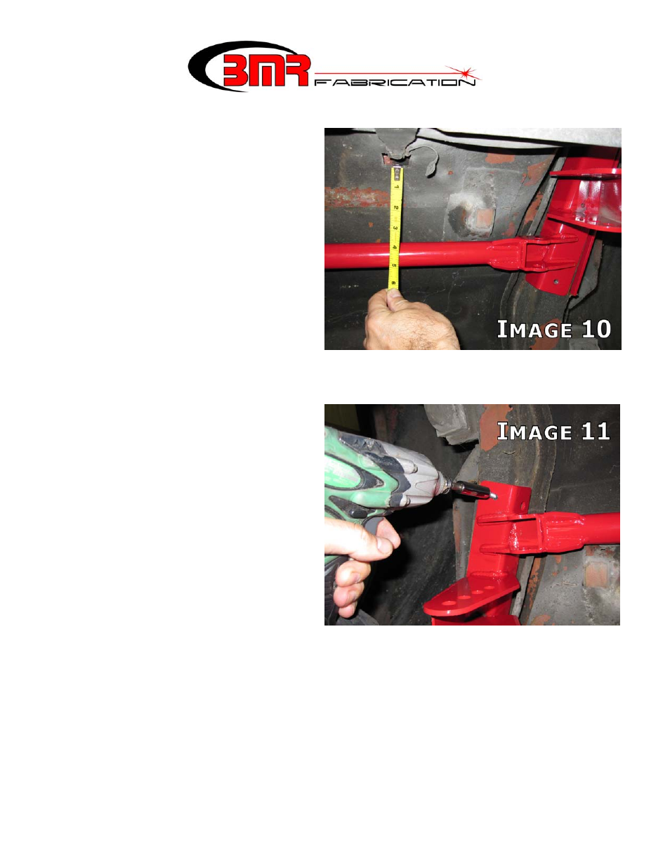
21. Use the fuel tank strap mounting
positions as a reference point to
locate the cross-member properly
front-to-back and to insure that the
cross-member is mounted square in
the body. As shown in Image 10,
measure the distance from the relief
in the trunk pan to the main cross
tube of the cross-member. Vehicle
production variance prevents a “one
measurement fits all” figure
but the measurements should fall
somewhere between 3-7/8” to 4-
1/16” when viewing the tape
measure from directly below.
Re-position the cross- member until
the reading from each strap mount relief is equal and falls within the range listed above.
22. Once properly positioned, locate the
provided sheet metal screws in the
hardware pack. As shown in Image
11, screw the cross-member into
each frame rail to hold it into
position for the upcoming steps.
NOTE: the cross-member should
draw up tight against the frame rail.
Any floor pan deformations that
prevent the cross-member from
fitting flush against the frame rail
should be adjusted using a pry-bar
or rubber mallet.
23. At this step the cross-member may be welded to the subframe or bolted. If bolting is
preferred, proceed to step 24. If welding is preferred, remove the cross-member and prep
it for welding by grinding the powdercoat off at the weld points. Remove all paint,
undercoating and scale from the weld area on the subframe then re-install the cross-
member. Weld a full 2” bead vertically on each end of the plate and at least 4 inches of
weld horizontally on each side. Wire brush and paint the weld area with rust preventive
paint. Proceed to step 30.
(CONTINUED)