BMR Suspension TAS001 User Manual
Page 8
8
(CONTINUED)
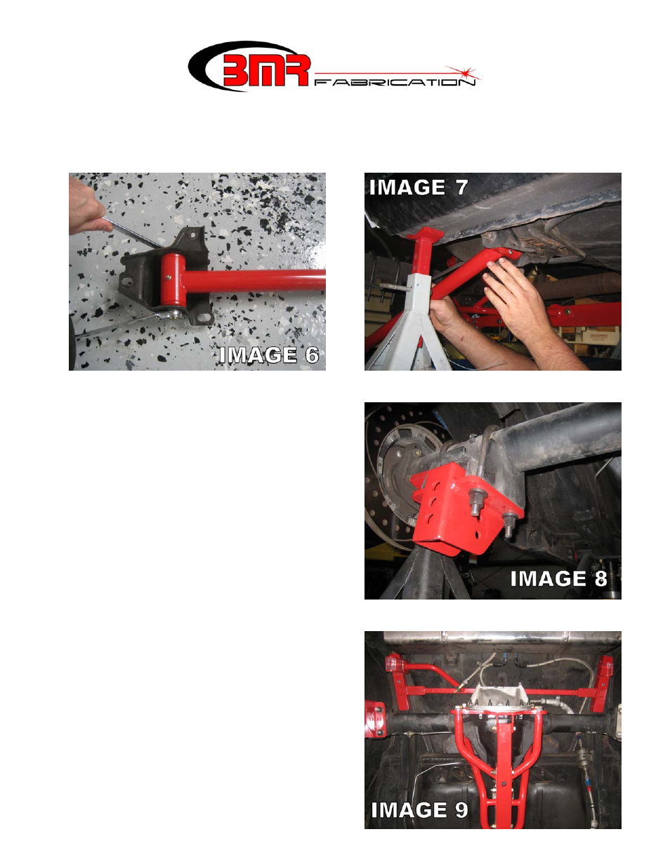
16. Install the BMR control arm mounts onto the axle using the supplied U-bolts. The open
portion of the mount should face forward as shown in Image 8. Tighten nuts to 90 ft/lbs.
17. Lift and insert the other end of the control arm into the axle brackets on the highest
mounting hole and insert the supplied ½” x
3.25” bolts. Place a stainless washer under
the nut but leave this connection loose until
a later step. NOTE: it may be necessary to
adjust the length of the control arms to
match the holes in the control arm mounts.
It may also be necessary to move the rear
end forward or back to line the mounting
holes up. If one trailing arm is adjusted,
duplicate this procedure on the other arm
and verify that they are equal in length
before proceeding to the next step.
18. The next step involves installation of the
shock cross-member. This step can be
performed by one person but is much simpler with a helper. Have a helper hold the
shock cross-member up into place as shown
in Image 9.
19. Use the fuel tank strap mounting positions
as a reference point to locate the cross-
member properly forward to back and to
insure that the cross-member is mounted
square in the body. As shown in Image 10,
measure the distance from the relief in the
trunk pan to the main cross tube of the
cross-member. Vehicle production variance
prevents a “one measurement fits all” figure