BMR Suspension SFC006 User Manual
Page 3
7. Using a wire wheel, remove all paint, rust, and scale from the weld areas surrounding the cut slot.
8. Locate the rear-most body mount bushing on the front subframe. Using a 15/16” socket, remove this bolt.
Loosen the next bolt forward also but do not remove it. The subframe should separate from the body
slightly.
9. Using a pry-bar, pry the subframe down until the factory body mount bushing can be removed. The
bushing is a two-piece design, one portion on top of the subframe and one below.
NOTE: depending on the condition of the vehicle, this area is subject to rust and scale. Before proceeding,
inspect the area for damage and repair, if necessary.
10. Slide one of the supplied frame boxes onto the rear of the subframe as shown in Image 4. Slide it as far
forward as possible.
11. Re-install the subframe connector into the cut portion of the floor pan.
12. Slide the frame box rearward until it fits flush against the end of the subframe connector.
13. Again pry downward on the subframe and insert the supplied BMR aluminum upper body mount bushing
from the top. Insert the supplied lower bushing along with the new bolt and washer then tighten the bolt.
14. Begin the welding process by stitch welding in multiple locations from front to back. If your cuts were
precise enough it is entirely possible to weld the entire perimeter top and bottom. NOTE: Take care
when welding the front frame box to the subframe connector that you do not burn the body mount
bushing. To accomplish this, weld one side at a time allowing cooling cycles between each step.
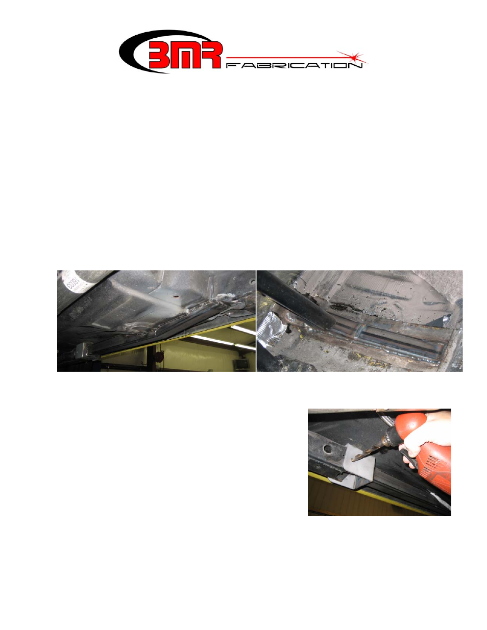
15. Lift the rear of the subframe connector up until it lines up with this bolt hole as shown in Image 3 below.
16. Wire wheel the entire weld then apply seam sealer to the area
followed by a rust preventative sealer or undercoat.
17. The front frame box can be bolted into place or welded to the
front subframe. Take note that bolting it into place permits the
removal of the front subframe while welding it in place is a
permanent solution.
18. If welding, proceed to step 20 below. If bolting into place, use
the holes in the front frame box as a drill-guide and drill two ½”
holes through the subframe. NOTE: It may be necessary to
remove the exhaust or use a 90 degree drill to gain access to the
inside drill area.
19. Insert the ½” x 1” bolts, washers and nuts into the holes and
tighten to 110 ft/lbs.
3