System maintenance switch – HP ProLiant DL320s Server User Manual
Page 12
Component identification 12
Item
Description Item
Description
1
PCI Express x8 connector
10
Fan 3 connector
2
PCI Express x1 connector
11
Fan 4 connector
3
System maintenance switch
(on page
12
Main power connector
4 NMI
13 Processor
socket
5
Battery
14
Auxiliary power connector
6
Front panel LED board
connector
15
DIMM slot 1 (bank A)
7
Internal USB connector
16
DIMM slot 2 (bank B)
8
Fan 1 connector
17
DIMM slot 3 (bank A)
9
Fan 2 connector
18
DIMM slot 4 (bank B)
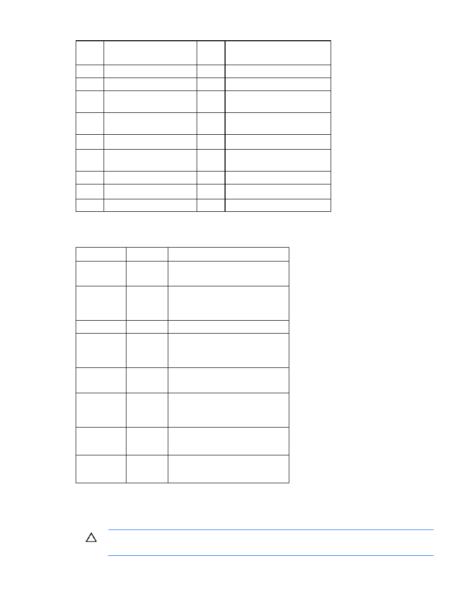
System maintenance switch
Position Default
Function
S1
Off
Off = iLO 2 security is enabled
On = iLO 2 security is disabled
S2
Off
Off = Normal operation
On = RBSU will not commit any
configuration changes *
S3 Off
Reserved
S4
Off
Off = Normal operation
On = Override RBSU setting and
enable diskette boot *
S5
Off
Off = Power-on password enabled
On = Power-on password disabled *
S6
Off
Off = Normal operation
On = BIOS will clear CMOS and
NVRAM *
S7 Off
Reserved
S8 Off
Reserved
* "On" activates the function.
When the system maintenance switch position 6 is set to the On position, the system is prepared to erase
all system configuration settings from both CMOS and NVRAM.
CAUTION:
Clearing CMOS and/or NVRAM deletes configuration information. Be sure to
properly configure the server or data loss could occur.