Installing the scsi interface cable, Figure 2-1 – HP Integrity NonStop H-Series User Manual
Page 30
Installing the Tape Drive
9840 (CT9840FC-3) Installation and User’s Guide for the NonStop S-Series Enclosure— 524959-003
2 -2
Installing the SCSI Interface Cable
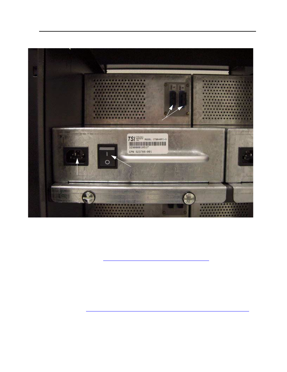
Figure 2-1. Location of Power Switch, AC Power Receptacle, and Fibre
Channel Connectors
Installing the SCSI Interface Cable
1. Before installing the 68-pin SCSI cable from the Fiber Channel converter to the
server, make sure that the tape drive and the Fibre Channel converter are both
powered off. Refer to
Appendix B, Multimode Fiber Optic Cables
for SCSI cable
part numbers.
2. Connect the 68-pin SCSI cable to the SCSI channel port on the Fibre Channel
converter.
3. Connect the other end of the 68-pin SCSI cable to a supported SCSI port on a
NonStop S-series server.
Refer to Section 1
Table 1-1, Supported SCSI Ports on the NonStop S-series Server,
AC Power Receptacle
Power Switch
Fibre Channel Connectors