Installation (b) (d) (a) (e) (c) – Ariston E-COMBI 24 30 38 User Manual
Page 16
16
installation
(b)
(d)
(a)
(e)
(c)
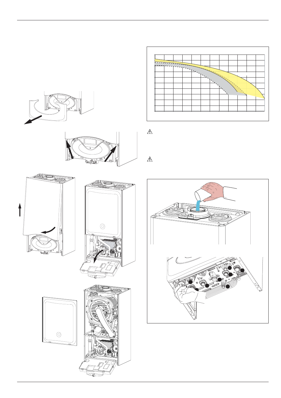
Instructions for opening the casing and performing an
internal inspection
Before performing any work on the boiler, fi rst disconnect it from the
electrical power supply using the external bipolar switch; removing
the fuse and shutting off the gas cock.
To access the inside of the boiler, the following is necessary:
1. Remove the casing by unhooking it from the control panel (a)
2. Loosen the two screws on the front casing (b), pull it forwards and
unhook it from the upper pins (c)
3. Lower the control panel (d)
4. Unhook the two clips on the combustion chamber panel and lift
off (e).
To calculate the size of the heating installation, refer to the "Available
pressure" graph below.
Graph representing the available circulation pump
pressure ΔT20
o
C
Before the equipment is used, for the fi rst time the trap must
be fi lled with water. To do this, add approximately 1/4 litre of
water via the fl ue outlet before fi tting the fl ue system, or uns-
crew the cap on the trap positioned underneath the boiler, fi ll
it with water and refi t it.
Warning!
Insuffi
cient water in the trap can temporarily cause the fl ue
gas to be expelled into the surrounding ambient air.
A
B
C
D
E
I
G
H
F
0
50
100
150
200
250
300
350
400
450
500
0
100
200
300
400
500
600
700
800
900
1000
1100
1200
mbar
l/h
24 kW
30-35 kW
30-38 kW