Connecting the alarm contacts – ADTRAN TRACER Protection Switch User Manual
Page 8
8
7
Connecting the Alarm Contacts
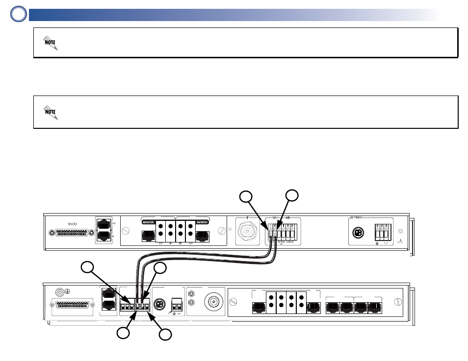
1. Connect the NO (Normally Open) alarm contact of the MAIN TRACER BBP (labeled 1 below) to the MN alarm contact in the IN alarm
block of the TRACER MPS (labeled 2 below). The TRACER BBP provides two sets of alarm contacts; for normal configuration, use
the NO located in the MAJ (Major Alarm) block.
2. Connect the COM (Common) alarm contact of the MAIN TRACER BBP (labeled 3 below) to the COM alarm contact in the IN alarm
block of the TRACER MPS (labeled 4 below). Repeat this step for the STANDBY TRACER BBP.
3. Connect the NO alarm contact of the STANDBY TRACER BBP to the SB alarm contact in the IN alarm block of the TRACER MPS
(labeled 5 below).
4. (OPTIONAL) Connect the TRACER MPS alarm contacts (NO, COM, NC) in the OUT alarm block (labeled 6 below) to your external
alarm monitoring system. Failure to follow this step will not affect TRACER MPS redundancy operation.
Only the TRACER 2603 BBP provides the optional MIN (Minor Alarm) terminal block. Connecting the MIN alarm contacts allows the
TRACER MPS to perform a system switch when a minor alarm condition occurs. Please refer to the TRACER 2603 User Manual
(ADTRAN P/N 61280003L1-1) for a detailed listing of major and minor alarms.
MANAGEMENT
T
R
A
C
E
R
MAIN
STANDBY
OUT
NO COM NC
MN COM SB
IN
ALARMS
DC POWER
RF
ANTENNA
TO DTE RS-232
MONITOR
T1B
T1A
MAIN
TRACER
STANDBY
TRACER
MONITOR
POWER
MODULE
USE COPPER
CONDUCTORS ONLY
OUT
IN
IN
OUT
B
A
B
A
MAIN
STAND
BY
T1B
T1A
MANAGEMENT
T
R
A
C
E
R
MAIN
STANDBY
OUT
NO COM NC
MN COM SB
IN
ALARMS
DC POWER
RF
ANTENNA
TO DTE RS-232
MONITOR
T1B
T1A
MAIN
TRACER
STANDBY
TRACER
MONITOR
POWER
MODULE
USE COPPER
CONDUCTORS ONLY
OUT
IN
IN
OUT
B
A
B
A
MAIN
STAND
BY
T1B
T1A
4
2
6
5
.
All alarm contact connections in the steps below should be made using standard 18 AWG insulated conductors. Insert the conductor in
the terminal block then use a flat-head screwdriver to secure the connection.
NO Alarm Contact
COM Alarm Contact
MN Alarm Contact
Connect to
External Alarm
System
COM Alarm Contact
SB Alarm Contact
3
1