7 watchpoint fault address register, 8 vector catch register, Table 11-11 – ARM Cortex R4F User Manual
Page 288: Data transfer register functions -19, Table 11-12, Watchpoint fault address register functions -19, Figure 11-6, Watchpoint fault address register format -19
Debug
ARM DDI 0363E
Copyright © 2009 ARM Limited. All rights reserved.
11-19
ID013010
Non-Confidential, Unrestricted Access
Table 11-11 shows how the bit values correspond with the DTRRX and DTRTX functions.
11.4.7
Watchpoint Fault Address Register
The Watchpoint Fault Address Register (WFAR) is a read/write register that holds the address
of the instruction that triggers the watchpoint.
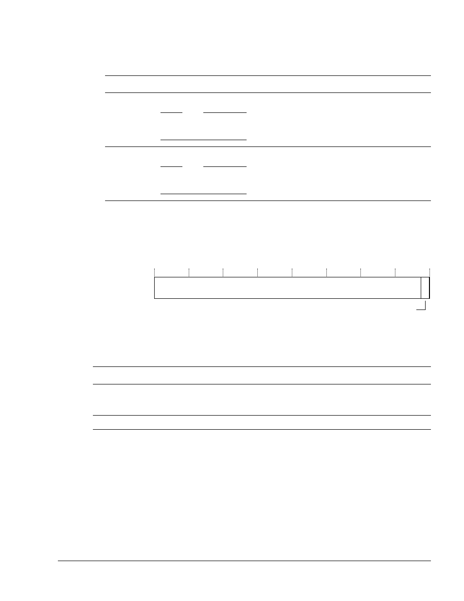
Figure 11-6 shows the bit arrangement of the Watchpoint Fault Address Register.
Figure 11-6 Watchpoint Fault Address Register format
Table 11-12 shows how the bit values correspond with the WFAR functions.
11.4.8
Vector Catch Register
The processor supports efficient exception vector catching. The read/write Vector Catch
Register controls this, as Figure 11-7 on page 11-20 shows.
Table 11-11 Data Transfer Register functions
Bits
Field
Function
[31:0]
Data
Reads the Data Transfer Register. This is read-only for the CP14 interface.
Note
Reads of the DTRRX through the coprocessor interface cause the DTRTXfull flag to be cleared.
However, reads of the DTRRX through the APB port do not affect this flag.
[31:0]
Data
Writes the Data Transfer Register. This is write-only for the CP14 interface.
Note
Writes to the DTRTX through the coprocessor interface cause the DTRRXfull flag to be set.
However, writes to the DTRTX through the APB port do not affect this flag.
Address
31
0
1
Reserved
Table 11-12 Watchpoint Fault Address Register functions
Bits
Field
Function
[31:1]
Address
This is the address of the watchpointed instruction. When a watchpoint occurs in ARM state, the
WFAR contains the address of the instruction causing it plus an offset of
0x8
. When a watchpoint
occurs in Thumb state, the offset is plus
0x4
.
[0]
Reserved
RAZ.