16 auxiliary control registers, Table 4-24, Auxiliary control register bit functions -38 – ARM Cortex R4F User Manual
Page 122: Figure 4-28, Auxiliary control register format -38
System Control Coprocessor
ARM DDI 0363E
Copyright © 2009 ARM Limited. All rights reserved.
4-38
ID013010
Non-Confidential, Unrestricted Access
Attempts to read or write the System Control Register from User mode results in an Undefined
exception.
4.2.16
Auxiliary Control Registers
The Auxiliary Control Registers control:
•
branch prediction
•
performance features
•
error and parity logic.
c1, Auxiliary Control Register
The Auxiliary Control Register is:
•
a read/write register
•
accessible in Privileged mode only.
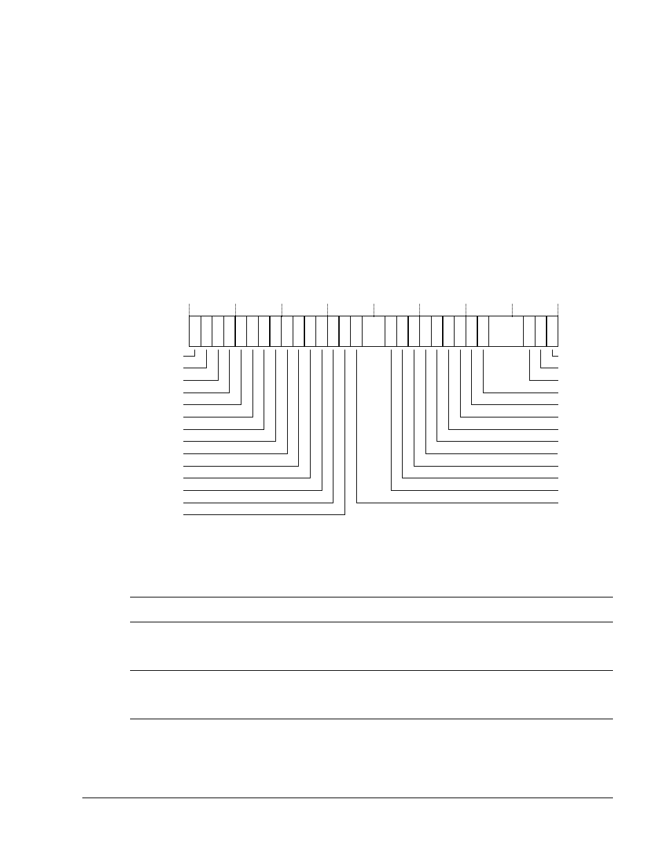
Figure 4-28 shows the arrangement of bits in the register.
Figure 4-28 Auxiliary Control Register format
Table 4-24 shows how the bit values correspond with the Auxiliary Control Register functions.
31
25 24 23 22 21
19 18 17 16 15 14 13 12 11
7 6
3 2 1 0
CEC
26
27
28
30 29
DIADI
10
20
DICDI
DIB2DI
DIB1DI
B1TCMPCEN
B0TCMPCEN
ATCMPCEN
AXISCEN
9
BP
5
8
AXISCUEN
DILSM
DEOLP
DBHE
FRCDIS
RSDIS
Reserved
ATCMECEN
B0TCMECEN
B1TCMECEN
DILS
sMOV
FDSnS
FWT
FORA
DNCH
ERPEG
DLFO
DBWR
Table 4-24 Auxiliary Control Register bit functions
Bits
Field Function
[31]
DICDI
a
Case C dual issue control:
0 = Enabled. This is the reset value.
1 = Disabled.
[30]
Case B2 dual issue control:
0 = Enabled. This is the reset value.
1 = Disabled.
[29]
Case B1 dual issue control:
0 = Enabled. This is the reset value.
1 = Disabled.