Raster line – Brother PJ-622 User Manual
Page 13
Brother PJ-600 Series Command Reference
11
© 2011 Brother Industries, Ltd. All Rights Reserved.
3.2.4.
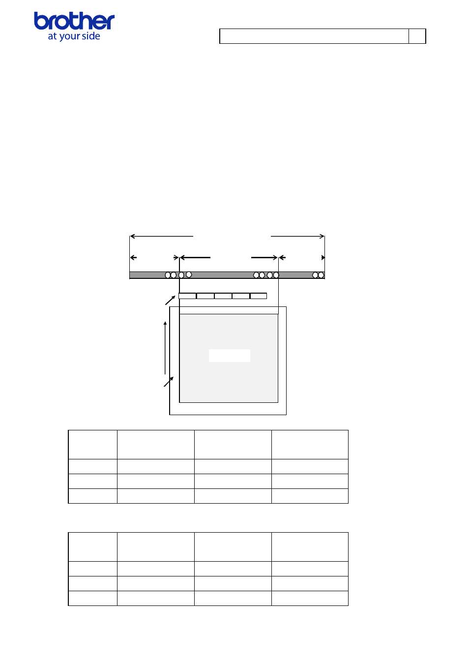
Raster line
The following shows how the raster is arranged on the pins of the print head according to "raster
graphics transfer".
The number of offset pins is calculated automatically based on the “set paper width” command and
centering the print area across the print head
The raster data specified with the “set left margin” and “1 raster line data transfer” commands is
reflected in the pins of the print area.
Furthermore, specified print data that extends out of the print area is automatically cut by the unit. In
addition, the page margins (in all directions) in the figure shown below have no effect on the raster
line.
0 pin
Paper
margin
First byte
Raster line
Feeding
direction
Print area
Pins
on print
head
Number of
print area
pins
Number
of unused
pins
Total number of pins
Number
of offset
pins
Total number of pins (300dpi) 2592
Paper Number
of
offset pins
Number of
Print area pins
Number of
unused pins
A4 96
2400
96
Legal 64 2464 64
Letter 64 2464 64
Total number of pins (200dpi) 1728
Paper Number
of
offset pins
Number of
Print area pins
Number of
unused pins
A4 64
1600
64
Legal 48 1632 48
Letter 48 1632 48