0 operation – Setra System Model 760 User Manual
Page 10
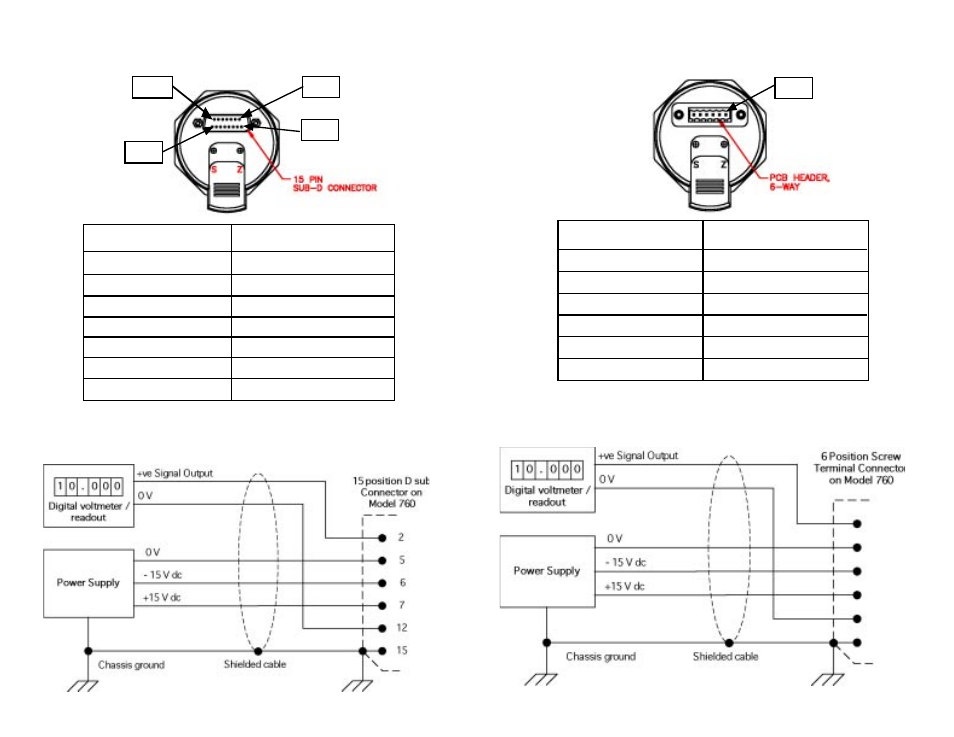
Figure 5: Pin out of D-sub Connector (Code D2)
Pin Location
Function
2
Signal Output
5
Power Supply Common
6
Power Supply, -15 VDC
7
Power Supply, + 15 VDC
12
Signal Output Common
15
Chassis Ground
1,3,4,8,9,10,11,13,14
Not used
Figure 6: Electrical Connection Schematic – D-sub 15-pin Connector
6
Pin 1
Pin 15
Pin 8
Pin 9
Figure 7 : Pin out of Screw Terminal Connector (Code T2):
Pin Location
Function
1
Power Supply Common
2
Signal Output Common
3
Signal Output
4
Power Supply, -15 VDC
5
Power Supply, + 15 VDC
6
Chassis Ground
Figure 8 : Electrical Connection Schematic - Screw Terminal Connector
7
Pin 1
3
1
4
5
2
6
See also other documents in the category Setra System Sensors:
- Model ASM (8 pages)
- Model 204 (4 pages)
- Model 209 (4 pages)
- Model 227 (8 pages)
- 264 (4 pages)
- 269 (4 pages)
- Model 280E (4 pages)
- Model 370 (48 pages)
- Model 526 (7 pages)
- Model 540 (9 pages)
- Model 595 (8 pages)
- Model 869 (28 pages)
- Model 321 (4 pages)
- Model SRH (12 pages)
- Model Datum 2000 (31 pages)
- Model 217 (8 pages)
- Model 230 (12 pages)
- Model 242901-06 (1 page)
- Model 265 (4 pages)
- Model 270 (5 pages)
- Model 299 (4 pages)
- Model 470 (35 pages)
- Model 524 (6 pages)
- Model 546 (8 pages)
- Model 730 (16 pages)
- GCT-225 (8 pages)
- Model 141 (4 pages)
- Model 205-2 (4 pages)
- Model 223 (8 pages)
- Model 231 (12 pages)
- Model 256 (8 pages)
- Model 276 (2 pages)
- Model 3100 (8 pages)
- Model 516 (6 pages)
- Model 550 (9 pages)
- Model LD330 (4 pages)
- Model SRMD (8 pages)
- Model 201 (4 pages)
- Setra Model 206 (4 pages)
- Model 224 (8 pages)
- Model 231RS (16 pages)
- 260 (2 pages)
- 267MR (14 pages)
- Model 278 (2 pages)