Mechanical mounting, Pitch and roll conventions, 3 mechanical mounting – PNI SeaTRAX User Manual
Page 14
PNI Sensor Corporation
DOC#1018154 r02
SeaTRAX User Manual
Page 9
4.3
Mechanical Mounting
For the SeaTRAX, the full-radius cut-outs along the long sides are intended for test fixturing
and not as the mechanical mount in the user’s system. PNI recommends securing the long
edge of the PCB to a shelf or lip in the user’s system using an adhesive. Ideally the
SeaTRAX also would be fully potted in the user’s system to reduce or eliminate shock and
vibration effects. Refer to Section 3.2 for dimensions, hole locations, and the reference frame
orientation.
Note: Ensure that when attaching the SeaTRAX to the host system, the mounting method does not
introduce stresses on the board, as this can affect the performance of the accelerometer, and
therefore also negatively affect heading accuracy.
4.3.1
Pitch and Roll Conventions
The SeaTRAX uses a MEMS accelerometer to measure the tilt angle of the heading
sensor. This data is output as pitch and roll data, and is also used in conjunction with the
magnetometers to provide a tilt-compensated heading reading.
The SeaTRAX utilizes Euler angles as the method for determining accurate orientation.
This method is the same used in aircraft orientation where the outputs are heading (also
called yaw or azimuth), pitch and roll. When using Euler angles, roll is defined as the
angle rotated around an axis through the center of the fuselage while pitch is rotation
around an axis through the center of the wings. These two rotations are independent of
each other since the rotation axes rotate with the plane body.
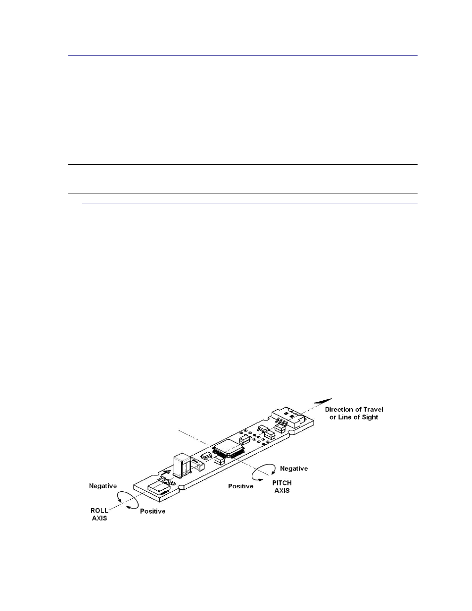
As shown in Figure 4-1, for the SeaTRAX a positive pitch is when the front edge of the
board is rotated upward and a positive roll is when the right edge of the board is rotated
downward.
Figure 4-1: Positive & Negative Roll and Pitch Definition