NORD Drivesystems BU0240 User Manual
Page 36
NORDAC SK 200E Manual
36
BU
0240
GB
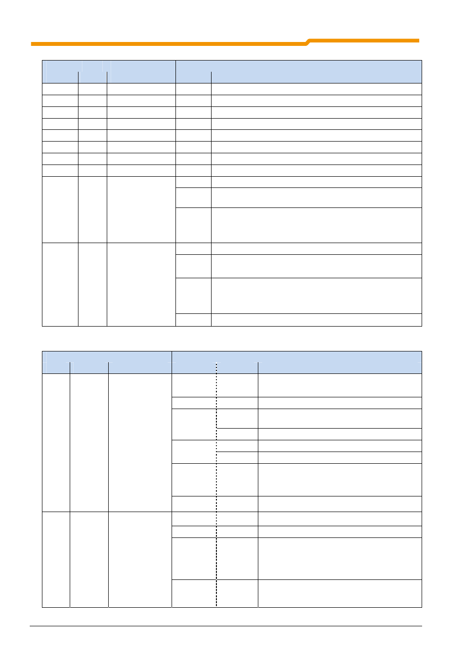
Diagnostic LEDs
LED
Signal
Name
Colour
Description
Status
Meaning
DOUT 1
yellow
Digital output 1
on
High signal applied
DIN 1
yellow
Digital input 1
on
High signal applied
DIN 2
yellow
Digital input 2
on
High signal applied
DIN 3
yellow
Digital input 3
on
High signal applied
DIN 4
yellow
Digital input 4
on
High signal applied
TEMP
yellow
Motor PTC
on
Motor overtemperature
Chop
yellow
Brake chopper
on
Brake chopper active, brightness →
degree of load
Brake
yellow
Mech. brake
on
Mech. Brake released
BUS-S
green
System bus status
off
No process data communication
Flashing
(4 Hz)
"BUS Warning"
on
Process data communication active
⇒ Reception of at least 1 telegram / s
⇒ SDO transfer is not indicated
BUS-E
green
System bus error
off
No error
Flashing
(4 Hz)
Monitoring error P120 or P513
⇒ E10.0 / E10.9
Flashing
(1 Hz)
Error in an external system bus module
⇒ Bus module Æ Timeout on the external BUS (E10.2)
⇒System bus module has a module error (E10.3)
on
System bus in state “BUS off”
Status LEDs
LED
Signal
Name
Colour
Description
Status
Meaning
DS
dual
red/green
Frequency
inverter status
off
FI not on standby,
⇒
no mains and control voltage
green
on
FI on standby
green
flashing
0.5 Hz
FI is ready for switch-on
2
Hz
FI is in switch-on block
red/green
0.5 Hz
Warning
alternating
1 … 25Hz
Degree of overload of switched-on FI
green on +
red flashing
FI not on standby,
⇒
Control voltage available but no mains
voltage
red
flashing
Error, flashing frequency →
Error number
AS-I
dual
AS-i status
off
No voltage to the AS-i module (PWR)
red/green
green
Normal
operation
red
No exchange of data
⇒
Slave Address = 0 / Slave not in LPS /
Slave with incorrect IO/ID /
Master in STOP mode / Reset active
alternately
flashing
red / green
Peripheral
error